
1. Software counting delays
In the first part of this tutorial, we will implement a naive delay function based on a software counting loop.
1.1. Delay implementation
Open your project and add a new source file delay.rs in your src folder:
// * delay.rs
//  *
//  *  Created on: 6 août 2017
//  *      Author: Laurent
//  *  Translated to Rust on: 22 avril 2022
//  *      Author: Paul

use core::arch::asm;
use stm32f0::stm32f0x2::Peripherals;

/*
 * Basic delay functions
 */

pub fn delay_ms(delay: u32) {
    let mut i = delay * 2500;
    while i > 0 {
        i -= 1;
    }
}

pub fn delay_us(delay: u32) {
    let mut i = delay * 3;
    while i > 0 {
        i -= 1;
    }
}
Note that both constants 2500 and 3 involved in the counting loops have been tuned by means of an oscilloscope to achieve expected delays. This tuning is only valid for the given clock settings (48MHz).
_Note: We use while loops instead of for loops in this case, because for loops in debug mode take a longer time than usual in Rust (more information on this subject)_
And finally, let us try something basic:
mod delay;

#[entry]
fn main() -> ! {
    // Get peripherals
    let peripherals = Peripherals::take().unwrap();

    // Configure System Clock
    let _fclk = system_clock_config(&peripherals).unwrap();

    // Initialize LED pin
    bsp::bsp_led_init(&peripherals);

    // Main loop
    loop {
        bsp::bsp_led_toggle(&peripherals);
        delay::delay_ms(500);
    }
}
Well, you should get a 1s period blinking LED. Fine!
1.2. Delay robustness
In the previous part we made a comment on the fact that for loops in Rust debug take longer time than they would in a release build (optimized build).
In this part we will compare the produced assembly code between the different optimization levels for the for and while loops.
Let's put back a for loop in our delay function so we can analyze these differences in depth.
#[inline(never)]
pub fn delay_ms(delay: u32) {
    for _ in 0..(delay * 2500) {
        unsafe { asm!("nop") }
    }
}
A few details have been added to the code:
#[inline(never)]avoids the function to be inlined (moved) to the main function when building with optimizationunsafe { asm!("nop") }adds aNOPoperation in assembly so that our loop is not empty (and won't be removed by the compiler when compiling with optimizations).
Here is the process to follow to inspect the assembly code:
-
We will use
cargo-asmto inspect assembly code. Go ahead and install it using the following command:cargo install cargo-asm -
Once its installed, just clean your last build to make sure we inspect the most recent assembly code:
cargo clean -
We now need to build the code... To emit assembly code when building, we need to specify a RUSTFLAG to the compiler. Run the following command:
RUSTFLAGS="--emit asm" cargo build -
As
cargo-asmlooks into thetarget/debugandtarget/releasefolders, we need to copy the assembly files to these folders:cp target/thumbv6m-none-eabi/debug/deps/*.s target/debug/deps -
We can now inspect the assembly code by running this command:
cargo asm --build-type debug my_project::delay::delay_ms
Here is the produced assembly code for the for loop with no optimization whatsoever:
my_project::delay::delay_ms (src/delay.rs:15):
 push    {r7, lr}
 add     r7, sp, #0
 sub     sp, #48
 str     r0, [sp, #40]
 ldr     r2, .LCPI13_0
 movs    r3, #0
 mov     r1, r3
 bl      __aeabi_lmul
 subs    r2, r1, #1
 sbcs    r1, r2
 str     r0, [sp, #12]
 cmp     r1, #0
 bne     .LBB13_2
 b       .LBB13_1
.LBB13_1:
 ldr     r0, [sp, #12]
 str     r0, [sp, #44]
 movs    r1, #0
 str     r1, [sp, #16]
 str     r0, [sp, #20]
 ldr     r0, [sp, #16]
 ldr     r1, [sp, #20]
 bl      _ZN63_$LT$I$u20$as$u20$core..iter..traits..collect..IntoIterator$GT$9into_iter17h0cce40ef77b47ad0E
 str     r0, [sp, #4]
 str     r1, [sp, #8]
 b       .LBB13_3
.LBB13_2:
 ldr     r0, .LCPI13_1
 ldr     r2, .LCPI13_2
 movs    r1, #33
 bl      _ZN4core9panicking5panic17hf0cea77c86777acfE
.LBB13_3:
 ldr     r0, [sp, #8]
 ldr     r1, [sp, #4]
 str     r1, [sp, #24]
 str     r0, [sp, #28]
 b       .LBB13_4
.LBB13_4:
 add     r0, sp, #24
 bl      _ZN4core4iter5range101_$LT$impl$u20$core..iter..traits..iterator..Iterator$u20$for$u20$core..ops..range..Range$LT$A$GT$$GT$4next17hdb4d4343b2f90a11E
 str     r1, [sp, #36]
 str     r0, [sp, #32]
 b       .LBB13_5
.LBB13_5:
 ldr     r0, [sp, #32]
 cmp     r0, #0
 beq     .LBB13_8
 b       .LBB13_6
.LBB13_6:
 b       .LBB13_9
.LBB13_8:
 add     sp, #48
 pop     {r7, pc}
.LBB13_9:
 @APP
 nop
 @NO_APP
 b       .LBB13_4
.LCPI13_0:
.LCPI13_1:
.LCPI13_2:
We can see that it contains a lot of lines, but most of all, it branches to these weird ..iter..traits..iterator sections, which take a lot of cycles to run...
If we launch a Debug session with this code, we can see that the LED takes a very very long time to blink. I counted 17 times longer...
If we try to replace our for loop with a while loop, like so:
#[inline(never)]
pub fn delay_ms(delay: u32) {
    let mut i = delay * 2500;
    while i > 0 {
        i -= 1;
        unsafe { asm!("nop") }
    }
}
We can now follow the same process to inspect to assembly code and we should get the following code:
my_project::delay::delay_ms (src/delay.rs:15):
 push    {r7, lr}
 add     r7, sp, #0
 sub     sp, #16
 str     r0, [sp, #12]
 ldr     r2, .LCPI13_0
 movs    r3, #0
 mov     r1, r3
 bl      __aeabi_lmul
 subs    r2, r1, #1
 sbcs    r1, r2
 str     r0, [sp, #4]
 cmp     r1, #0
 bne     .LBB13_2
 b       .LBB13_1
.LBB13_1:
 ldr     r0, [sp, #4]
 str     r0, [sp, #8]
 b       .LBB13_3
.LBB13_2:
 ldr     r0, .LCPI13_3
 ldr     r2, .LCPI13_4
 movs    r1, #33
 bl      _ZN4core9panicking5panic17hf0cea77c86777acfE
.LBB13_3:
 ldr     r0, [sp, #8]
 cmp     r0, #0
 bne     .LBB13_5
 b       .LBB13_4
.LBB13_4:
 add     sp, #16
 pop     {r7, pc}
.LBB13_5:
 ldr     r0, [sp, #8]
 subs    r1, r0, #1
 str     r1, [sp]
 cmp     r0, #1
 blo     .LBB13_7
 b       .LBB13_6
.LBB13_6:
 ldr     r0, [sp]
 str     r0, [sp, #8]
 @APP
 nop
 @NO_APP
 b       .LBB13_3
.LBB13_7:
 ldr     r0, .LCPI13_1
 ldr     r2, .LCPI13_2
 movs    r1, #33
 bl      _ZN4core9panicking5panic17hf0cea77c86777acfE
.LCPI13_0:
.LCPI13_1:
.LCPI13_2:
.LCPI13_3:
.LCPI13_4:
We can see that the assembly code that we produced is not that different in length than for our for loop (54 lines now, compared to 60 lines before), but we no longer have calls to any iterator (..iter..). If we run a Debug session, we can see that the LED is blinking at around a 1Hz rate as intended...
But what happens if we optimize our code?
We can optimize the code by adding the following lines at the end of the Cargo.toml file:
[profile.dev]
opt-level = 1
We start by only optimizing using the 1st optimization level (we can go up to 3, click here for more information on opt-levels).
We can now inspect the produced assembly code for this while loop (optimized with opt-level=1):
my_project::delay::delay_ms (src/delay.rs:15):
 push    {r7, lr}
 add     r7, sp, #0
 ldr     r0, .LCPI1_0
.LBB1_1:
 @APP
 nop
 @NO_APP
 adds    r0, r0, #1
 blo     .LBB1_1
 pop     {r7, pc}
.LCPI1_0:
We can see that optimizing a while loop with opt-level=1 does reduce quite a lot the amount of assembly lines generated.
And if we look at the assembly code of the for loop (optimized with opt-level=1):
my_project::delay::delay_ms (src/delay.rs:15):
 push    {r4, r6, r7, lr}
 add     r7, sp, #8
 movs    r0, #0
 movs    r1, #1
 ldr     r2, .LCPI1_0
 mov     r4, r1
 mov     r3, r0
 b       .LBB1_2
.LBB1_1:
 @APP
 nop
 @NO_APP
 cmp     r3, r2
 bhs     .LBB1_4
.LBB1_2:
 ands    r4, r1
 adds    r3, r3, r4
 cmp     r3, r2
 mov     r4, r1
 blo     .LBB1_1
 mov     r4, r0
 b       .LBB1_1
.LBB1_4:
 pop     {r4, r6, r7, pc}
.LCPI1_0:
Once again the amount of assembly lines is reduced, but most importantly, we have no more calls to ..iter... This generated assembly code is smaller than the one generated without optimization, but it is still much longer than the one generated for the while loop with the same level of optimization.
If we go to the maximum optimization level (opt-level=3), we can see that for and while compile to the same assembly code.
my_project::delay::delay_ms (src/delay.rs:15):
 push    {r7, lr}
 add     r7, sp, #0
 ldr     r0, .LCPI1_0
.LBB1_1:
 @APP
 nop
 @NO_APP
 subs    r0, r0, #1
 bne     .LBB1_1
 pop     {r7, pc}
.LCPI1_0:
This generated assembly code is also the same than the one generated for the while loop with opt-level=1. This means that our while loop is easier to optimize than our for loop.
The fact is that optimization level changes the way your Rust code translates into assembly code, making it more and more efficient as optimization level increases. Using optimization level different from opt-level=0 (used when building for debug) needs special care as optimizer removes everything considered as “useless” (including operations and variables). Code that is useless to the optimizer is not always useless to you. A debug message for example, or intermediate variables can disappear. So, beware with optimizations, and it is always a good idea to start writing code with no optimizations. This way, you are sure to find what you expect from the debugger.
The purpose of the above experiment was to explain that timing based on software counting is very dependent on external parameters such as code optimization, or clock source/frequency. It is therefore advisable to implement delays with more robust approaches.
2. Timer as time-base
2.1. Simple time-base
There are up to 12 hardware timers available in the STM32F072 device. These timers are not all the same, as some of them boast larger counter width or other advanced features.
In order to setup a simple delay, let us pick-up a basic 16-bit timer with few features: TIM6
A timer is basically a counter (CNT). The counting speed is defined by both the bus clock frequency fclk and its 16-bit prescaler (PSC) value:
$$f{counter}=\frac{f{clk}}{PSC+1}$$
When the counter reaches a given value stored in its 16-bit Auto-Reload Register (ARR), it goes back to zero and generate an update event by setting its UIF flag to 1. The period between two successive update events is therefore:
$$T{update}=\frac{ARR+1}{f{counter}}$$
Let's say we want to implement a 1s delay with TIM6. TIM6 is connected to APB1 which runs at 48MHz.
- Setting PSC = (48000 -1) → we get a 1ms counting period
- Setting ARR = (1000 -1) → we get a 1s period between update events
Note that solution is not unique. Setting PSC = (24000 -1) and ARR = (2000 -1) provides the same result. The difference is in the delay range/resolution you can achieve by adjusting the ARR value. The table below provides some working examples. Basically increasing the delay range implies a decrease in the delay tuning resolution.
| PSC +1 | ARR +1 | Update period min | Update period max | Resolution/ARR |
|---|---|---|---|---|
| 48000 | 1000 | 2ms | 65.535s | 1ms |
| 24000 | 2000 | 1ms | 32.7675s | 500µs |
| 12000 | 4000 | 500µs | 16.38375s | 250µs |
| ... |
In summary, you must choose the PSC value (within 16-bit range) according to the resolution you want given that ARR must also fit into the 16-bit range.
Note that TIM2 is a 32-bit counter, if you need longer delay while keeping the resolution high enough.
First, add the following function implementation to bsp.rs:
/*
 * bsp_timer_timebase_init()
 * TIM6 at 48MHz
 * Prescaler   = 48000 -> Counting period = 1ms
 * Auto-reload = 1000  -> Update period   = 1s
 */
pub fn bsp_timer_timebase_init(peripherals: &Peripherals) {
    let (rcc, tim6) = (&peripherals.RCC, &peripherals.TIM6);

    // Enable TIM6 clock
    rcc.apb1enr.modify(|_, w| w.tim6en().enabled());

    // Reset TIM6 configuration
    tim6.cr1.reset();
    tim6.cr2.reset();

    // Set TIM6 prescaler
    // Fck = 48MHz -> /48000 = 1KHz counting frequency
    tim6.psc.modify(|_, w| w.psc().bits((48000 - 1) as u16));

    // Set TIM6 auto-reload register for 1s
    tim6.arr.modify(|_, w| w.arr().bits((1000 - 1) as u16));

    // Enable auto-reload preload
    tim6.cr1.modify(|_, w| w.arpe().enabled());

    // Start TIM6 counter
    tim6.cr1.modify(|_, w| w.cen().enabled());
}
Now, change the main function into this simple code that continuously:
- puts the content of TIM6->CNT into a
tim6_countervariable - toggles the
tim6_uifvariable between 0 and 1024 every time UIF flag is set
#[entry]
fn main() -> ! {
    // Variables
    let (mut tim6_counter, mut tim6_uif): (u16, u16) = (0, 0);

    // Get peripherals
    let peripherals = Peripherals::take().unwrap();
    let tim6 = &peripherals.TIM6;

    // Configure System Clock
    let _fclk = system_clock_config(&peripherals).unwrap();

    // Initialize LED pin and console
    bsp::bsp_led_init(&peripherals);
    let mut console = bsp::bsp_console_init(&peripherals);

    // Initialize and start time base
    bsp::bsp_timer_timebase_init(&peripherals);

    // Main loop
    loop {
        // Get actual counter value
        tim6_counter = tim6.cnt.read().cnt().bits();

        // If UIF is set
        if tim6.sr.read().uif().bit_is_set() {
            // Toggle tim6_uif between 0 and 1024
            tim6_uif ^= 0x01 << 10;

            // Reset UIF
            tim6.sr.modify(|_, w| w.uif().clear());
        }

        // Print values of counter and uif every 100ms
        if (tim6_counter % 100) == 0 {
            print!(
                console,
                "\r\nCounter value = {}\r\nUIF flag = {}\r\n", tim6_counter, tim6_uif
            );
        }
    }
}
If we look into the console, we can see that the UIF flag alternates between 0 and 1024 when the counter value hits 1000.

If we were to trace the values of the counter and the uif flag, we would obtain the following graph:
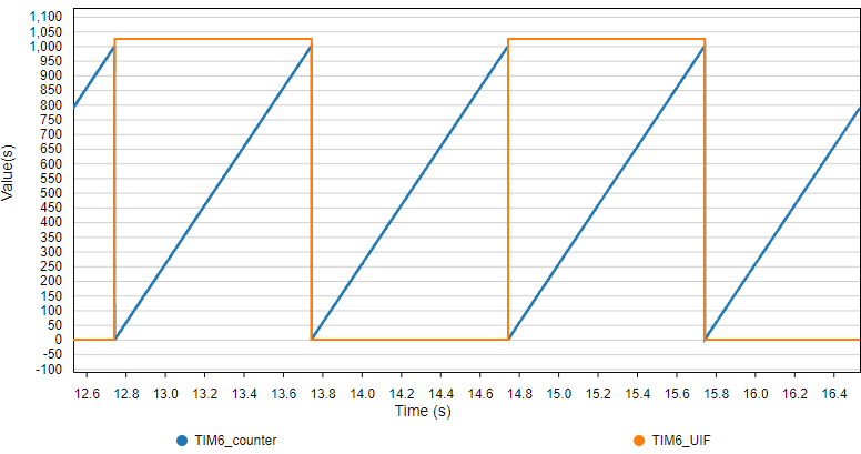
As expected, the counter keep counting from 0 to 1000 and then resets. Every time a reset occurs, the UIF flag is set. Period between UIF events is 1000ms. All is well.
2.2. Timer as a robust delay function
Let us write a new delay function based on TIM6. Add this first function implementation in delay.rs:
/*
 * timer_delay_init()
 * Initialize TIM6 with 1ms counting period
 * ARR is set to maximum value -> delay [2ms-65s]
 */

pub fn timer_delay_init(peripherals: &Peripherals) {
    let (rcc, tim6) = (&peripherals.RCC, &peripherals.TIM6);

    // Enable TIM6 clock
    rcc.apb1enr.modify(|_, w| w.tim6en().enabled());

    // Reset TIM6 configuration
    tim6.cr1.reset();
    tim6.cr2.reset();

    // Set TIM6 prescaler
    // Fck = 48MHz -> /48000 = 1KHz counting frequency
    tim6.psc.modify(|_, w| w.psc().bits((48000 - 1) as u16));

    // Set ARR to maximum value
    tim6.arr.modify(|_, w| w.arr().bits(0xFFFF as u16));
}
This function basically only set the timer prescaler PSC in order to achieve a 1ms counting period. We are not going to use the update event, therefore ARR is set to maximum in order to allow full range counting (16-bit = 0 → 65535). The maximum possible delay is thus 65.535ms.
The delay function is somehow plain. We’re just loop polling the counter register CNT until it reaches the desired waiting time:
/*
 * timer_delay_ms(delay: u16)
 * waits here for delay
 */

pub fn timer_delay_ms(peripherals: &Peripherals, delay: u16) {
    let tim6 = &peripherals.TIM6;

    // Resets TIM6 counter
    // TIM6->EGR |= TIM_EGR_UG;
    tim6.egr.write(|w| w.ug().update());

    // Start TIM6 counter
    tim6.cr1.modify(|_, w| w.cen().enabled());

    // Wait until TIM6 counter reaches delay
    while tim6.cnt.read().bits() < delay as u32 {}

    // Stop TIM6 counter
    tim6.cr1.modify(|_, w| w.cen().disabled());
}
A quick check in main.rs:
#[entry]
fn main() -> ! {
    // Get peripherals
    let peripherals = Peripherals::take().unwrap();

    // Configure System Clock
    let _fclk = system_clock_config(&peripherals).unwrap();

    // Initialize LED pin
    bsp::bsp_led_init(&peripherals);

    // Initialize and start time base
    delay::timer_delay_init(&peripherals);

    // Main loop
    loop {
        // Toggle LED
        bsp::bsp_led_toggle(&peripherals);

        // Wait for 200ms
        delay::timer_delay_ms(&peripherals, 200);
    }
}
Save the code (Ctrl + S) and start a debug session to check the blinking LED.
Then change optimization to opt-level=1. Clean all, run a debug session again. The delay is not changed by optimization level this time. That's really interesting because you can now optimize other parts of the code for faster execution, without compromising the delay function.
Come back to opt-level=0 after this.
3. Timer as input capture
Timers have associated channels you can use to measure or drive timing-based events on I/O pins.
- Input capture mode is used when you need to measure a delay
- Output compare mode is used when you need to drive a signal with precise timing
Let us first illustrate Input Capture mode. In the following example, we will measure the duration user button is pushed down.
3.1. Single edge capture
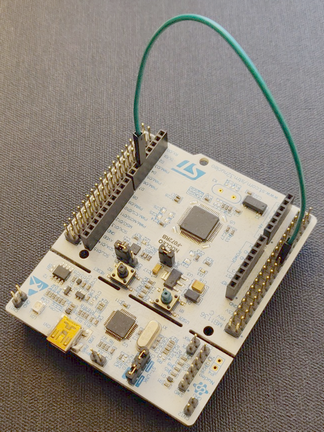
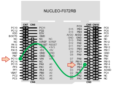
We need first to select an available timer, and a pin that we can use as timer channel. We can pick-up timer 3 (TIM3) and pin PB4 which corresponds to TIM3 Channel 1 when used in its Alternate Function 1 (AF1):
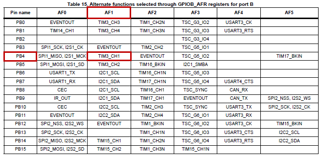
In order to connect the user button to PB4, you must fit a bond wire between PC13 and PB4. Doing so connects the user button to TIM3 Channel 1. Remember that PC13 is high when button is released, and low when button is pushed down.
A function that initializes TIM3 to work as input capture of Channel 1 is given below. The function does the following
- Enable GPIOB clock and setup PB4 for AF1 (TIM3 Channel 1)
- Enable TIM3 clock
- Setup TIM3 prescaler according the timing resolution we want (1ms)
- Set the auto-reload value at maximum so that counter can reach 216.
- Associate Channel 1 with trigger input 1 (PB4)
- Setup input capture on the falling edge of Channel 1
Add this function to your bsp.rs:
/*
 * bsp_timer_ic_init()
 * TIM3 as Input Capture
 * Channel 1 -> PB4 (AF1)
 */

// void BSP_TIMER_IC_Init()
pub fn bsp_timer_ic_init(peripherals: &Peripherals) {
    let (rcc, gpiob, tim3) = (&peripherals.RCC, &peripherals.GPIOB, &peripherals.TIM3);

    // Enable GPIOB clock
    rcc.ahbenr.modify(|_, w| w.iopben().enabled());

    // Configure PB4 as Alternate function
    gpiob.moder.modify(|_, w| w.moder4().alternate());

    // Set PB4 to AF1 (TIM3_CH1)
    gpiob.afrl.modify(|_, w| w.afrl4().af1());

    // Enable TIM3 clock
    rcc.apb1enr.modify(|_, w| w.tim3en().enabled());

    // Reset TIM3 configuration
    tim3.cr1.reset();
    tim3.cr2.reset();
    tim3.ccer.reset();

    // Set TIM3 prescaler
    // Fck = 48MHz -> /48000 = 1KHz counting frequency
    tim3.psc.modify(|_, w| w.psc().bits(48000 - 1 as u16));

    // Set Auto-Reload to maximum value
    tim3.arr.modify(|_, w| w.arr().bits(0xFFFF as u16));

    // Reset Input Capture configuration
    tim3.ccmr1_input().reset();
    tim3.ccmr2_input().reset();

    // Set Channel 1 input on TI1
    tim3.ccmr1_input().modify(|_, w| w.cc1s().ti1());

    // Filter with N=8
    tim3.ccmr1_input().modify(|_, w| w.ic1f().fck_int_n8());

    // Select falling edge for channel 1
    tim3.ccer
        .modify(|_, w| w.cc1np().clear_bit().cc1p().set_bit());

    // Enable capture on channel 1
    tim3.ccer.modify(|_, w| w.cc1e().set_bit());

    // Enable TIM3
    tim3.cr1.modify(|_, w| w.cen().enabled());
}
And now we can test something simple in main.rs:
#[entry]
fn main() -> ! {
// Get peripherals
let peripherals = Peripherals::take().unwrap();
let tim3 = &peripherals.TIM3;
// Configure System Clock
let _fclk = system_clock_config(&peripherals).unwrap();
// Initialize Console
let mut console = bsp::bsp_console_init(&peripherals);
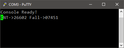
print!(console, "Console Ready!\r\n");
// Initialize and start time base
delay::timer_delay_init(&peripherals);
// Initialize timer for input capture
bsp::bsp_timer_ic_init(&peripherals);
// Main loop
loop {
// Report TIM3 status (CNT and CCR1 registers)
print!(
console,
"CNT->{} Fall->{}\r\n",
tim3.cnt.read().bits(),
tim3.ccr1.read().bits()
);
// Wait for 100ms
delay::timer_delay_ms(&peripherals, 100);
}
}
Console displays TIM3 counter value by polling its CNT register every 100ms. When you press the blue button, the actual CNT value is saved in CCR1 register giving you the precise moment the falling edge occurs. This is the very basic functionality of Input Capture mode.
Note that there is no code in main() function to test the state of the button. Timer is doing everything by itself…
OK. If we want to measure the pulse duration, we also need to capture the rising event that occurs when button is released. Let us do that...
3.2. Dual edges capture
Edit the previous bsp_timer_ic_init() function as follows:
...
    // Reset Input Capture configuration
    tim3.ccmr1_input().reset();
    tim3.ccmr2_input().reset();

    // Set Channel 1 input on TI1
    tim3.ccmr1_input().modify(|_, w| w.cc1s().ti1());

    // Channel 2 input also on TI1
    tim3.ccmr1_input().modify(|_, w| w.cc2s().ti1());

    // Filter both channels with N=8
    tim3.ccmr1_input()
        .modify(|_, w| w.ic1f().bits(0x03).ic2f().bits(0x03));

    // Select falling edge for channel 1
    tim3.ccer
        .modify(|_, w| w.cc1np().clear_bit().cc1p().set_bit());

    // Select rising edge for channel 1
    tim3.ccer
        .modify(|_, w| w.cc2np().clear_bit().cc2p().clear_bit());

    // Enable capture on channel 1 and channel 2
    tim3.ccer.modify(|_, w| w.cc1e().set_bit().cc2e().set_bit());

    // Enable TIM3
    tim3.cr1.modify(|_, w| w.cen().enabled());
...
We’ve enabled the timer Channel 2 as input capture. It is associated to the rising edge of trigger input 1 (PB4).
Let us now see what Channel 2 captures using this updated main function:
#[entry]
fn main() -> ! {
// Get peripherals
let peripherals = Peripherals::take().unwrap();
let tim3 = &peripherals.TIM3;
// Configure System Clock
let _fclk = system_clock_config(&peripherals).unwrap();
// Initialize Console
let mut console = bsp::bsp_console_init(&peripherals);
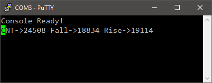
print!(console, "Console Ready!\r\n");
// Initialize and start time base
delay::timer_delay_init(&peripherals);
// Initialize timer for input capture
bsp::bsp_timer_ic_init(&peripherals);
// Main loop
loop {
// Report TIM3 status (CNT and CCR1 registers)
print!(
console,
"CNT->{} Fall->{} Rise->{}\r\n",
tim3.cnt.read().bits(),
tim3.ccr1.read().bits(),
tim3.ccr2.read().bits()
);
// Wait for 100ms
delay::timer_delay_ms(&peripherals, 100);
}
}
Now, when you play with the blue button, you get a catch of CNT value for both falling and rising edges.
That is enough to compute the time the button is kept low. You can just perform the (CCR2 – CCR1) time subtraction and get the pulse width. If you do so, you need to take care of the counter overflow (around $2^{16}$).
Could we go further and free the CPU up from calculating the pulse width, and prevent counter overflow by the way? The answer is YES…
3.3. Dual edges capture with slave reset
The idea is to use the first (falling) edge to reset the timer counter. Doing so, the value caught in CCR2 would directly represent the pulse duration. And as long as the pulse is less that 65s, there is no risk of counter overflow.
Edit the previous bsp_timer_ic_init() function as follows:
...
    // Reset Input Capture configuration
    tim3.ccmr1_input().reset();
    tim3.ccmr2_input().reset();

    // Channel 1 input on TI1
    tim3.ccmr1_input().modify(|_, w| w.cc1s().ti1());

    // Channel 2 input also on TI1
    tim3.ccmr1_input().modify(|_, w| w.cc2s().ti1());

    // Filter both channels with N=8
    tim3.ccmr1_input()
        .modify(|_, w| w.ic1f().bits(0x03).ic2f().bits(0x03));

    // Select falling edge for channel 1
    tim3.ccer
        .modify(|_, w| w.cc1np().clear_bit().cc1p().set_bit());

    // Select rising edge for channel 1
    tim3.ccer
        .modify(|_, w| w.cc2np().clear_bit().cc2p().clear_bit());

    // Enable capture on channel 1 and channel 2
    tim3.ccer.modify(|_, w| w.cc1e().set_bit().cc2e().set_bit());

    // Choose Channel 1 as trigger input
    tim3.smcr.modify(|_, w| w.ts().ti1fp1());

    // Slave mode -> Resets counter when trigger occurs
    tim3.smcr.modify(|_, w| w.sms().reset_mode());

    // Enable TIM3
    tim3.cr1.modify(|_, w| w.cen().enabled());
...
Update main function as CCR2 now holds the pulse length:
#[entry]
fn main() -> ! {
// Get peripherals
let peripherals = Peripherals::take().unwrap();
let tim3 = &peripherals.TIM3;
// Configure System Clock
let _fclk = system_clock_config(&peripherals).unwrap();
// Initialize Console
let mut console = bsp::bsp_console_init(&peripherals);
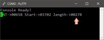
print!(console, "Console Ready!\r\n");
// Initialize and start time base
delay::timer_delay_init(&peripherals);
// Initialize timer for input capture
bsp::bsp_timer_ic_init(&peripherals);
// Main loop
loop {
// Report TIM3 status (CNT and CCR1 registers)
print!(
console,
"CNT->{} Start->{} length->{}\r\n",
tim3.cnt.read().bits(),
tim3.ccr1.read().bits(),
tim3.ccr2.read().bits()
);
// Wait for 100ms
delay::timer_delay_ms(&peripherals, 100);
}
}
Now, when you press the button:
- CCR1 holds the copy of actual CNT value (start time)
- CNT resets to 0x0000
When you release the button:
- CCR2 holds a copy of actual CNT (i.e. the time you’ve kept the button down)
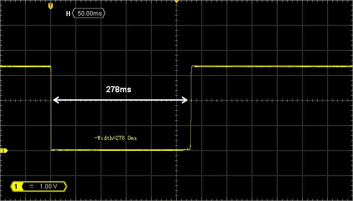
If you have an oscilloscope at hand, probe PB4 and measure the time you keep the button pushed down. Compare with the length that the console reports. You should have a match within 1ms error.
With these settings, the last pulse length is now always available in TIM3 CCR2 register, without any CPU intervention. You can use such timer configuration to convert a PWM signal into a data. This is very handy to read RC controller output (among other applications).
4. Timer as output compare: PWM generation
4.1. What is a PWM signal?
Figure below shows an example of a PWM signal. PWM stands for “Pulse Width Modulation”. In short, you take a square signal and move along the time axis only one of his edges (it can be either the rising or the falling edge). Figure below illustrates a PWM signal with a moving falling edge. Only one edge is moving, therefore the period T of the PWM signal is constant. Moving one edge changes the duty cycle (w/T) in a range between 0% (when w=0) to 100% (when w=T).
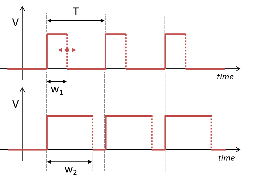
Timings of a digital PWM signal are defined by:
- Its period T (s)
- Its resolution (s). The resolution is the smallest possible change in the width w.
- Its duty cycle range (i.e. wmin, wmax).
Let us take an example: servomotors control.
4.2. Servomotors as practical example
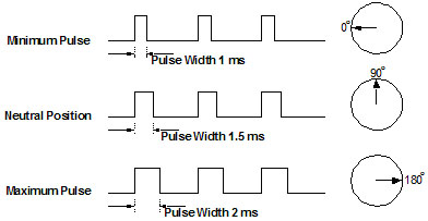
Servomotors are analog or digital devices converting input signal into an angular position of the wheel. Input signal is a pulse width ranging from 1ms to 2ms, with an arbitrary period (a common period for servomotors is 11ms).
When using 180° range servomotor, you get the left position (0°) with a 1ms pulse, a neutral position (90°)with a 1.5ms pulse and the right position (180°) with a 2ms pulse.
Now, say that we want to control the servomotor with at least 0.2° resolution. That means that we need about 180/0.2 = 900 discrete values for our pulse width. Let us round off this result to 1000 values.
4.3. Timer setup of PWM output
Say we want to simultaneously control 2 servomotors with one timer. We can pick up channels 1 and 2 of timer 1 (TIM1), mapped on pin PA8 and PA9 using their alternate function AF2.
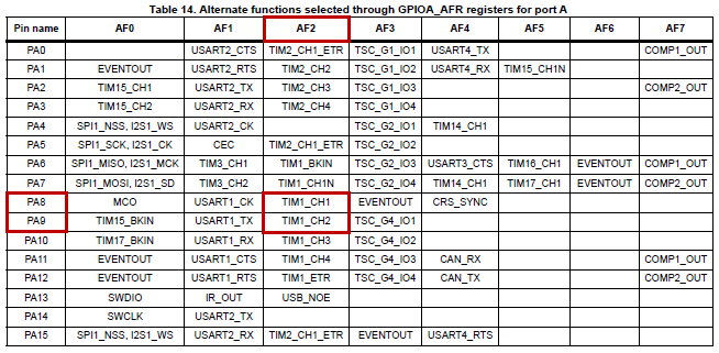
Note that PA8 is already in use in our project as MCO pin (3MHz Master Clock Output). We are not going to use MCO anyway, so let things be. The following configuration will override the PA8 function.
Our PWM specifications:
- A period T of 11ms
- A pulse width ranging from 1ms to 2ms
- A resolution corresponding to 1000 values between 1ms and 2ms = 1µs resolution
STM32 timers can be used to generate PWM signals by using the OC (Output Compare) feature. OC is a mechanism by which you can automatically generate events when the timer counter reaches chosen values.
Add the following function to bsp.rs:
/*
 * bsp_timer_pwm_init()
 * TIM1 as Output Compare PWM mode
 * Channel 1 -> PA8 (AF2)
 * Channel 2 -> PA9 (AF2)
 */

pub fn bsp_timer_pwm_init(peripherals: &Peripherals) {
    let (rcc, gpioa, tim1) = (&peripherals.RCC, &peripherals.GPIOA, &peripherals.TIM1);

    // Enable GPIOA clock
    rcc.ahbenr.modify(|_, w| w.iopaen().enabled());

    // Configure PA8 and PA9 as Alternate Function
    gpioa
        .moder
        .modify(|_, w| w.moder8().alternate().moder9().alternate());

    // Set PA8 and PA9 to AF2 (TIM1)
    gpioa.afrh.modify(|_, w| w.afrh8().af2().afrh9().af2());

    // Enable TIM1 clock
    rcc.apb2enr.modify(|_, w| w.tim1en().enabled());

    // Reset TIM1 configuration
    tim1.cr1.reset();
    tim1.cr2.reset();
    tim1.ccer.reset();

    // Set TIM1 prescaler
    // Fck = 48MHz -> /48 = 1MHz counting frequency (1µs resolution)
    tim1.psc.modify(|_, w| w.psc().bits(48 - 1 as u16));

    // Set Auto-Reload to period = 11ms
    tim1.arr.modify(|_, w| w.arr().bits(11000 as u16));

    // Enable Auto-Reload Preload register
    tim1.cr1.modify(|_, w| w.arpe().enabled());

    // Setup Input Capture
    tim1.ccmr1_input().reset();
    tim1.ccmr2_input().reset();

    // Setup PWM mode 1 output
    tim1.ccmr1_output()
        .modify(|_, w| w.oc1m().pwm_mode1().oc1pe().enabled());
    tim1.ccmr1_output()
        .modify(|_, w| w.oc2m().pwm_mode1().oc2pe().enabled());

    // Set default PWM values
    tim1.ccr1.modify(|_, w| w.ccr().bits(1500));
    tim1.ccr2.modify(|_, w| w.ccr().bits(1500));

    // Enable Outputs
    tim1.ccer.modify(|_, w| w.cc1e().set_bit().cc2e().set_bit());

    // Enable Main output
    tim1.bdtr.modify(|_, w| w.moe().enabled());

    // Enable TIM1
    tim1.cr1.modify(|_, w| w.cen().enabled());
}
As soon as you call bsp_timer_pwm_init() from the main function, the timer start working as configured independently from the CPU activity. Try this and you’ll be sure:
#[entry]
fn main() -> ! {
    // Get peripherals
    let peripherals = Peripherals::take().unwrap();

    // Configure System Clock
    let _fclk = system_clock_config(&peripherals).unwrap();

    // Initialize timer for pwm output
    bsp::bsp_timer_pwm_init(&peripherals);

    // Main loop
    loop {
        // CPU is doing nothing here, and forever...
    }
}
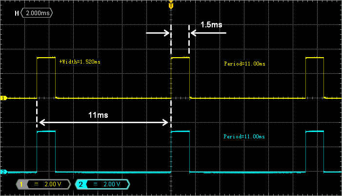
Probing PA8 and PA9 with an oscilloscope reveals the two PMW signals as expected. Period is 11ms and pulse width is 1.5ms.
Let us now write a small state machine to real-time module both pulse lengths between 1ms and 2ms (to mimic servomotor command):
#[entry]
fn main() -> ! {
    // Variables
    let (mut pulse_a, mut pulse_b): (u16, u16) = (1500, 1500);
    let mut state: bool = false;

    // Get peripherals
    let peripherals = Peripherals::take().unwrap();
    let tim1 = &peripherals.TIM1;

    // Configure System Clock
    let _fclk = system_clock_config(&peripherals).unwrap();

    // Initialize timer for delays
    bsp::bsp_timer_timebase_init(&peripherals);

    // Initialize timer for pwm output
    bsp::bsp_timer_pwm_init(&peripherals);

    // Main loop
    loop {
        // Set PWMs duty ratios according to pulse_a and pulse_b values
        tim1.ccr1.write(|w| w.ccr().bits(pulse_a));
        tim1.ccr2.write(|w| w.ccr().bits(pulse_b));

        // Manage state machine
        if state {
            // Increasing B, Decreasing A
            pulse_a -= 1;
            pulse_b += 1;

            // Stop condition -> State 0
            if pulse_b == 2000 {
                state = false;
            }
        } else {
            // Increasing A, Decreasing B
            pulse_a += 1;
            pulse_b -= 1;

            // Stop condition -> State 1
            if pulse_a == 2000 {
                state = true;
            }
        }

        // Wait for 2ms
        delay::timer_delay_ms(&peripherals, 2);
    }
}
Observe the two PWM outputs on the oscilloscope. Figure below has been obtained by setting infinite persistence on the oscilloscope to reveal the time range of falling edges. Does the range of pulse widths match the servomotor input range?
5. Summary
Timers are complex peripherals able to perform a variety of time-related tasks. This tutorial covered few applications including:
- Time base generation and simple delays implementation
- Input capture mode for measuring external pulse duration
- Output compare for PWM signal generation