
1. Debug Console
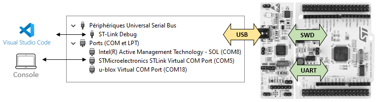
When you open the Windows peripheral manager, you can see that connecting the Nucleo board to the computer with USB adds 2 devices to the peripheral list.
- The ST-Link Debug is the device we already use to program and debug the MCU. Communication between the ST-Link and the MCU is done via the Serial Wire Debug (SWD) protocol.
- The second device is a virtual COM Port (COM5 in the example below). Such COM port can be used to exchange user data between the computer and the MCU. Typically, this link is used to implement console functions such as print!(). The link between the ST-Link and the MCU is a Universal Asynchronous Receiver Transmitter interface (UART).
On Linux, unplug you device and plug it back in. Then, run this command in a terminal:
$ sudo dmesg | more

[ 7588.884395] usb 1-2: USB disconnect, device number 2
[ 7588.895440] FAT-fs (sda): unable to read boot sector to mark fs as dirty
[ 7591.344345] usb 1-2: new full-speed USB device number 8 using xhci_hcd
[ 7591.498400] usb 1-2: New USB device found, idVendor=0483, idProduct=374b, bcd
Device= 1.00
[ 7591.498413] usb 1-2: New USB device strings: Mfr=1, Product=2, SerialNumber=3
[ 7591.498418] usb 1-2: Product: STM32 STLink
[ 7591.498422] usb 1-2: Manufacturer: STMicroelectronics
[ 7591.498425] usb 1-2: SerialNumber: 066AFF544949878667152437
[ 7591.559609] usb-storage 1-2:1.1: USB Mass Storage device detected

...skipping 1 line
[ 7591.560584] cdc_acm 1-2:1.2: ttyACM0: USB ACM device
[ 7592.593316] scsi 3:0:0:0: Direct-Access     MBED     microcontroller  1.0  PQ
: 0 ANSI: 2
[ 7592.593948] sd 3:0:0:0: Attached scsi generic sg0 type 0
[ 7592.594478] sd 3:0:0:0: [sda] 840 512-byte logical blocks: (430 kB/420 KiB)
[ 7592.594730] sd 3:0:0:0: [sda] Write Protect is off
[ 7592.594736] sd 3:0:0:0: [sda] Mode Sense: 03 00 00 00
[ 7592.594905] sd 3:0:0:0: [sda] No Caching mode page found
[ 7592.594913] sd 3:0:0:0: [sda] Assuming drive cache: write through
[ 7592.615202] sd 3:0:0:0: [sda] Attached SCSI removable disk
We can see that our Linux system picked up on the disconnection/reconnection of our board and shows us a bunch of information on our board (Product, Manufacturer, SerialNumber, etc.). It also indicates the port on which our COM port has been mounted, in our case, it is ttyACM0.
Linux mounts devices as files under the /dev/ folder. Hence, the full path for our COM port is /dev/ttyACM0.
You can use any serial terminal program to emulate the console. Here we will use PuTTy (www.putty.org).
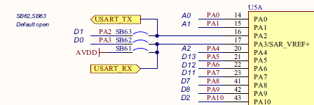
This virtual COM port is connected to UART (or USART) pins on the MCU. Looking at the schematics, it appears that PA2 is used for TX (transmission) and PA3 is used for RX (reception).
- UART stands for Universal Asynchronous Receiver Transmitter
- USART stands for Universal Asynchronous Synchronous Receiver Transmitter
In a Synchronous communication scheme, there is one additional wire that carries a clock signal. This is optional, and we will only use the Asynchronous protocol (UART). STM32 peripherals are mostly USART that can work in both modes. In the following USART or UART words are used with no difference in mind.
2. USART setup
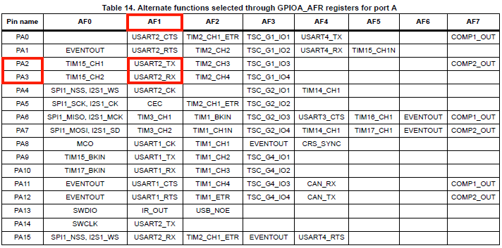
Opening the STM32F072 datasheet, we can find that PA2 and PA3 are associated to USART2 peripheral, in the AF1 mode (Alternate Function 1):
We will first implement a driver function that initializes USART2 to work with the virtual COM port.
Open my_project and add the functions bsp.rs. You need to refer to the reference manual to understand the code below. Basically, you need to configure 2 peripherals:
- GPIOA →Set PA2 and PA3 in AF1 mode (USART2)
- USART2 → Communications settings (such as the Baud Rate)
/*
 * bsp_console_init()
 * USART2 @ 115200 Full Duplex
 * 1 start - 8-bit - 1 stop
 * TX -> PA2 (AF1)
 * RX -> PA3 (AF1)
 */

pub fn bsp_console_init(peripherals: &Peripherals) {
    let (rcc, gpioa, usart2) = (&peripherals.RCC, &peripherals.GPIOA, &peripherals.USART2);

    // Enable GPIOA clock
    rcc.ahbenr.modify(|_, w| w.iopaen().enabled());

    // Configure PA2 and PA3 as Alternate function
    gpioa
        .moder
        .modify(|_, w| w.moder2().alternate().moder3().alternate());

    // Set PA2 and PA3 to AF1 (USART2)
    gpioa.afrl.modify(|_, w| w.afrl2().af1().afrl3().af1());

    // Enable USART2 clock
    rcc.apb1enr.modify(|_, w| w.usart2en().enabled());

    // Clear USART2 configuration (reset state)
    // 8-bit, 1 start, 1 stop, CTS/RTS disabled
    usart2.cr1.reset();
    usart2.cr2.reset();
    usart2.cr3.reset();

    // Select PCLK (APB1) as clock source
    // PCLK -> 48 MHz
    rcc.cfgr3.modify(|_, w| w.usart2sw().pclk());

    // Baud Rate = 115200
    // With OVER8=0 and Fck=48MHz, USARTDIV =   48E6/115200 = 416.6666
    // BRR = 417 -> Baud Rate = 115107.9137 -> 0.08% error
    //
    // With OVER8=1 and Fck=48MHz, USARTDIV = 2*48E6/115200 = 833.3333
    // BRR = 833 -> Baud Rate = 115246.0984 -> 0.04% error (better)

    usart2.cr1.modify(|_, w| w.over8().oversampling8());
    usart2.brr.modify(|_, w| w.brr().bits(833));

    // Enable both Transmitter and Receiver
    usart2.cr1.modify(|_, w| w.te().enabled().re().enabled());

    // Enable USART2
    usart2.cr1.modify(|_, w| w.ue().enabled());
}
Now we can try something in main.rs:
mod bsp;

#[entry]
fn main() -> ! {
    let mut sent: bool = false;
    // Get peripherals
    let peripherals = Peripherals::take().unwrap();
    let usart2 = &peripherals.USART2;

    // Configure System Clock
    let _fclk = system_clock_config(&peripherals).unwrap();

    // Initialize LED & User-Button pin
    bsp::bsp_led_init(&peripherals);
    bsp::bsp_pb_init(&peripherals);

    // Initialize Debug Console
    bsp::bsp_console_init(&peripherals);

    // Main loop
    loop {
        // Turn LED On if User-Button is pushed down
        if bsp::bsp_pb_get_state(&peripherals) {
            bsp::bsp_led_on(&peripherals);

            // Send '#' only once
            if !sent {
                while usart2.isr.read().tc().bit_is_clear() {}
                usart2.tdr.write(|w| w.tdr().bits('#' as u16));
                sent = true;
            }
        }
        // Otherwise turn LED Off
        else {
            bsp::bsp_led_off(&peripherals);
            sent = false;
        }
    }
}
The code above calls the initialization function. Then, every time you press the user button the character ‘#’ is put into the Transmit Data Register (TDR) of USART2, after making sure that USART2 is not busy by checking state of its Transfer Complete (TC) flag.
Save the code (Ctrl + S) and start a debug session.
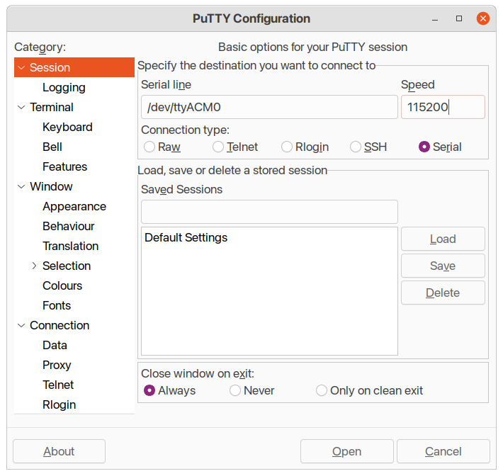
Launch a Serial terminal program on the previously identified Serial port at 115200 bauds. Below example illustrate the configuration of PuTTy:
Then play with the Nucleo user-button (blue). You should see a ‘#’ being printed each time the button is pressed:
TODO: Capture screenshot of PuTTY with '#' printed
Good! But we still don’t have a print function available. We can only send character one by one. Don’t be afraid, you will not have to code your own print function (but we're not too far from this...)
3. Getting print to work
We could have created a function called print, that takes a string as an argument and only executes a foor loop containing our two line to send the characters via UART serial communication. However, we wouldn't support formatting...
Formatting for printed outputs enables us to personnalize how data will be printed in the console, by positioning our string-formatted variable in a bigger string.
For example using C language, formatting can look like this:
printf("This is the value: %d\n", my_variable);
To support formatting, we have to implement the core::fmt::Write trait for a structure which will be used as an output stream for the write function. We will call our structure Console as it will be used to print to our console interface (PuTTY).
Create the src/console.rs file and fill it with the following content:
/*
 *  Console struct
 *  Paul Delestrac & Loïc France - 20/04/2022
 */

use core::fmt::{write, Arguments, Result as FmtResult, Write};
use stm32f0::{self as _, stm32f0x2::USART2};

// Declaring print macro
#[macro_export]
macro_rules! print {
    ($term:ident,$($arg:tt)*) => {
        $term.write(format_args!($($arg)*))
    };
}

// Declaring Console struct
pub struct Console<'a> {
    // CHANGE PERIPHERAL IF NEEDED
    pub uart: &'a USART2,
}

// Implementing write method
impl Console<'_> {
    pub fn write(&mut self, args: Arguments<'_>) {
        _ = write(self, args);
    }
}

// Implementing Write trait
impl Write for Console<'_> {
    fn write_str(&mut self, _s: &str) -> FmtResult {
        for c in _s.chars() {
            _ = self.write_char(c);
        }
        return Ok(());
    }

    fn write_char(&mut self, c: char) -> FmtResult {
        // CHANGE THIS FUNCTION TO FIT USED PERIPHERAL

        while self.uart.isr.read().tc().bit_is_clear() {}
        self.uart.tdr.write(|w| w.tdr().bits(c as u16));

        return Ok(());
    }
}
Let us try to explain this code...
-
printmacroThis macro enables us to use a call
print!()macro to call ourwritemethod. -
Consolestructure (pub struct Console)First, we create a structure
Consolewhich is composed of anuartvariable of typestm32f0::stm32f0x2::USART2.This is the most frustrating part of this structure... The package we use was automatically generated using the svd2rust crate. This crate is a very useful tool, but treats all the peripherals as different types. This means that
USART1,USART2andUSART3are three different types, even if they are all UART peripherals. This makes our code less easy to port to other boards as not all board connect the UART console toUSART2..._If you want to port this code on another board, or MCU, you will need to change the imported crate
stm32f0, the number of theUSARTxport to use and even thewrite_charfunction (if the peripherals registers need to be used differently). For this, you should refer to your board's reference manual._ -
Console'swritemethodThis function implements the
core::fmt::writemethod for ourConsolestructure, which enables formatting support. -
Console'sWritetraitThis trait implements how we print characters to our console (i.e., filling them into the
UARTTDRregister).
Before changing our src/main.rs file, let us change our bsp_console_init() function so that it initializes our Console structure:
pub fn bsp_console_init(peripherals: &Peripherals) -> Console {
    let (rcc, gpioa, usart2) = (&peripherals.RCC, &peripherals.GPIOA, &peripherals.USART2);

    // Enable GPIOA clock
    rcc.ahbenr.modify(|_, w| w.iopaen().enabled());

    // Configure PA2 and PA3 as Alternate function
    gpioa
        .moder
        .modify(|_, w| w.moder2().alternate().moder3().alternate());

    // Set PA2 and PA3 to AF1 (USART2)
    gpioa.afrl.modify(|_, w| w.afrl2().af1().afrl3().af1());

    // Enable USART2 clock
    rcc.apb1enr.modify(|_, w| w.usart2en().enabled());

    // Clear USART2 configuration (reset state)
    // 8-bit, 1 start, 1 stop, CTS/RTS disabled
    usart2.cr1.reset();
    usart2.cr2.reset();
    usart2.cr3.reset();

    // Select PCLK (APB1) as clock source
    // PCLK -> 48 MHz
    rcc.cfgr3.modify(|_, w| w.usart2sw().pclk());

    // Baud Rate = 115200
    // With OVER8=0 and Fck=48MHz, USARTDIV =   48E6/115200 = 416.6666
    // BRR = 417 -> Baud Rate = 115107.9137 -> 0.08% error
    //
    // With OVER8=1 and Fck=48MHz, USARTDIV = 2*48E6/115200 = 833.3333
    // BRR = 833 -> Baud Rate = 115246.0984 -> 0.04% error (better)

    usart2.cr1.modify(|_, w| w.over8().oversampling8());
    usart2.brr.modify(|_, w| w.brr().bits(833));

    // Enable both Transmitter and Receiver
    usart2.cr1.modify(|_, w| w.te().enabled().re().enabled());

    // Enable USART2
    usart2.cr1.modify(|_, w| w.ue().enabled());

    return Console { uart: usart2 };
}
Don't forget the import at the top of our src/bsp.rs:
use crate::console::Console;
We can now change our src/main.rs to include a call to our new print macro:
#[entry]
fn main() -> ! {
    let mut sent: bool = false;
    // Get peripherals
    let peripherals = Peripherals::take().unwrap();

    // Configure System Clock
    let _fclk = system_clock_config(&peripherals).unwrap();

    // Initialize LED & User-Button pin
    bsp::bsp_led_init(&peripherals);
    bsp::bsp_pb_init(&peripherals);

    // Initialize Debug Console
    let mut console = bsp::bsp_console_init(&peripherals);

    // Main loop
    loop {
        // Turn LED On if User-Button is pushed down
        if bsp::bsp_pb_get_state(&peripherals) {
            bsp::bsp_led_on(&peripherals);

            // Send '#' only once
            if !sent {
                print!(console, "#");
                sent = true;
            }
        }
        // Otherwise turn LED Off
        else {
            bsp::bsp_led_off(&peripherals);
            sent = false;
        }
    }
}
Don't forget the import at the top of our src/main.rs:
#![no_std]
#![no_main]

use panic_halt as _;
use stm32f0 as _;

use cortex_m_rt::entry;
use stm32f0::stm32f0x2::Peripherals;

mod bsp;
mod console;    // <-- Add this line
Save the code (Ctrl + S) and start a debug session to verify that everything still works.
4. Summary
Now you have a working print macro.
You should bear in mind that using print takes time because it relies on a slow serial interface. For instance, the message "Console Ready!\r\n" takes about $1.4ms$ to print at 115200 bauds. It is quite long considering what CPU would be able to do in such a long time.
Screenshot below shows the USART signal corresponding the "Console Ready!\r\n" message. You can probe it using the RX pin header available on the ST-Link dongle (PA2 and PA3 pin headers are actually disconnected from the MCU. Refer to board schematics).
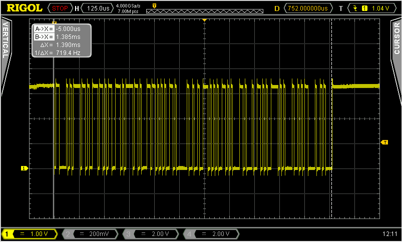
During the print process, CPU is spending most time waiting for USART to be available for the next character to be sent. Although using print is of great help while debugging, you should be aware that it will dramatically slow down code execution.
Here are some hints to make things better:
- Use of Semihosting feature instead of USART. It only works under debugger control, whereas our
printfunction works even in standalone running applications. Nevertheless, Semihosting can be slower than using the USART. - Avoid long messages. Ultimately, you can send only one character by directly loading USART TDR register. This process does not involve any waiting time since the USART sending process is parallel to CPU execution. It is not applicable to strings but might be really helpful. Use it when you want to real-time monitor code checkpoints.
- You can fully parallelize the USART sending process of strings by using DMA (more on this later).
- The baud rate may be increased way past standard RS232 baud rates since actual signal is carried thru USB which is a fast serial interface. Baud rates up to 1M bauds work fine.
- STM32CubeMonitor can help you spy variables, in real-time with no effect on execution performance.