
1. Introduction
This tutorial is dedicated to the implementation of few BSP functions. In the world of embedded systems, BSP stands for “Board Support Package”. In simple words, it is a collection of functions to address on-board components such as I/Os, displays, sensors, communication interfaces… A collection of functions that simplifies the software interface with a given peripheral is also called a library, or a driver. Nucleo boards are rather poor in terms of accessories. Basically, you have a user LED, a user button, and a serial interface through the ST-Link dongle. LEDs and Buttons are directly interfaced with MCU pins in output or input modes. These are configured by means of GPIO (General Purpose Input Output) peripherals.
2. Starting project and first commit
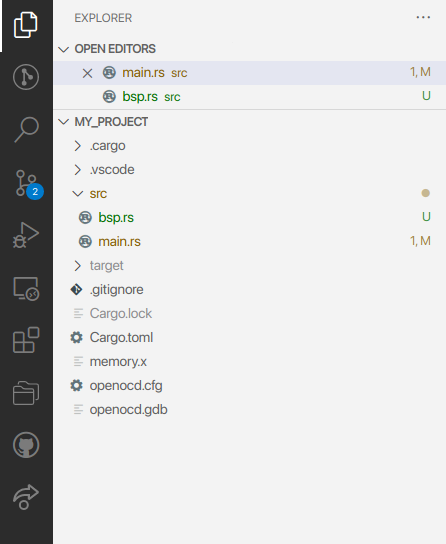
Start VSCode and open my_project project. At this step, my_project is a rather clean starting project you've created by cloning blink project project. my_project project will be used all along subsequent tutorials.
We will start by some housework to get a clean starting point. In the main() function, remove the LED blinking code. In the SystemClock_Config(), we don't need the MCO on PA8 anymore as it was there only to monitor clock frequency. When done, your main.rs may look like this (without taking into account system_core_clock_update which should stay unchanged at the bottom of the main.rs file):
#![no_std]
#![no_main]

use panic_halt as _;
use stm32f0 as _;

use cortex_m_rt::entry;
use stm32f0::stm32f0x2::Peripherals;

#[entry]
fn main() -> ! {
    // Get peripherals
    let peripherals = Peripherals::take().unwrap();

    // Configure System Clock
    let fclk = system_clock_config(&peripherals).unwrap();

    loop {}
}

/*
 *  Clock configuration for the Nucleo STM32F072RB board
 *  HSE input Bypass Mode    -> 8MHz
 *  SYSCLK, AHB, APB1    -> 48MHz
 *
 *  Laurent Latorre - 05/08/2017
 *  Translated to Rust by Paul Delestrac - 15/04/2022
 */
#[derive(Debug)]
enum ClockConfigError {
    HSEError,
    PLLError,
    SWError,
}

fn system_clock_config(peripherals: &Peripherals) -> Result<u32, ClockConfigError> {
    let (mut hse_status, mut pll_status, mut sw_status): (bool, bool, bool);
    let mut timeout: i32;

    let rcc = &peripherals.RCC;
    let flash = &peripherals.FLASH;

    // Start HSE in Bypass Mode
    rcc.cr.modify(|_, w| w.hsebyp().bypassed().hseon().on());

    // Wait until HSE is ready
    timeout = 1000;
    loop {
        hse_status = rcc.cr.read().hserdy().is_ready();
        timeout -= 1;
        if (hse_status) || (timeout <= 0) {
            break;
        };
    }

    if timeout == 0 {
        return Err(ClockConfigError::HSEError); // HSE Error
    };

    // Select HSE as PLL input source
    rcc.cfgr.modify(|_, w| w.pllsrc().hse_div_prediv());

    // Set PLL Prediv to /1
    rcc.cfgr2.modify(|_, w| w.prediv().div1());

    // Set PLL MUL to x6
    rcc.cfgr.modify(|_, w| w.pllmul().mul6());

    // Enable the main PLL
    rcc.cr.modify(|_, w| w.pllon().on());

    // Wait until PLL is ready
    timeout = 1000;
    loop {
        pll_status = rcc.cr.read().pllrdy().is_ready();
        timeout -= 1;
        if (pll_status) || (timeout <= 0) {
            break;
        };
    }

    if timeout == 0 {
        return Err(ClockConfigError::PLLError); // PLL Error
    };

    // Set AHB and APB1 prescaler to /1
    rcc.cfgr.modify(|_, w| w.hpre().div1().ppre().div1());

    // Enable FLASH Prefetch Buffer and set Flash Latency (required for high speed)
    flash
        .acr
        .modify(|_, w| w.prftbe().enabled().latency().ws1()); //

    // Select the main PLL as system clock source
    rcc.cfgr.modify(|_, w| w.sw().pll());

    // Wait until PLL becomes main switch input
    timeout = 1000;
    loop {
        sw_status = rcc.cfgr.read().sws().is_pll();
        timeout -= 1;
        if (sw_status) || (timeout <= 0) {
            break;
        }
    }

    if timeout == 0 {
        return Err(ClockConfigError::SWError); // SW Error
    }

    // Return core clock frequency value
    return Ok(system_core_clock_update(&peripherals));
}
Save the code (Ctrl + S) and start a debug session to make sure there is no error or warning. Verify fclk value...
3. LED driver
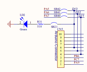
A look at the board schematics tells us that the green user LED is connected to the pin PA5 of the MCU. Given that LED cathode goes to ground, the LED is "ON" when PA5 is at its high logic voltage.
Let us take a moment to think about what functions we would like to have in order to play with the LED:
- A function that turn the LED on
- A function that turn the LED off
- A function that toggle the LED state
Note that it would have been possible to use a single function that sets the LED state using an argument (ON/OFF/Toggle). That's a matter of taste...
We know that a MCU pin needs to be configured to serve as an output. If we include the pin configuration into the previous functions, it will be done every time we want to change the LED state. This is a waste of both CPU time and power consumption as configuration does not change once it is done. Therefore, let us write a separate function to address pin configuration, that will be called only once at the beginning of the main code.
Create a new source file bsp.rs under bsp/ folder.
Open, edit bsp.rs and write the functions.
In the following, the function belongs to the BSP, concerns the LED, and its purpose is the initialization of the MCU pin. Let’s name the function bsp_led_init():
// * bsp.rs
//  *
//  *  Created on: 5 août 2017
//  *      Author: Laurent
//  *  Translated to Rust on: 15 avril 2022
//  *      Author: Paul

use stm32f0::stm32f0x2::Peripherals;

/*
 * bsp_led_init()
 * Initialize LED pin (PA5) as a High-Speed Push-Pull output
 * Set LED initial state to OFF
 */
pub fn bsp_led_init(peripherals: &Peripherals) {
    let rcc = &peripherals.RCC;
    let gpioa = &peripherals.GPIOA;

    // Enable GPIOA clock
    rcc.ahbenr.modify(|_, w| w.iopaen().enabled());

    // Configure PA5 as output
    gpioa.moder.modify(|_, w| w.moder5().output());

    // Configure PA5 as Push-Pull output
    gpioa.otyper.modify(|_, w| w.ot5().push_pull());

    // Configure PA5 as High-Speed Output
    gpioa.ospeedr.modify(|_, w| w.ospeedr5().high_speed());

    // Disable PA5 Pull-up/Pull-down
    gpioa.pupdr.modify(|_, w| w.pupdr5().floating());

    // Set Initial State OFF
    gpioa.bsrr.write(|w| w.br5().reset());
}
You must refer to the reference manual for a complete description of RCC AHBENR register, and GPIO MODER, OTYPER, OSPEEDR, PUPDR, BSRR registers.
Next comes the three controlling functions:
/*
 * bsp_led_on()
 * Turn ON LED on PA5
 */

pub fn bsp_led_on(peripherals: &Peripherals) {
    let gpioa = &peripherals.GPIOA;
    gpioa.bsrr.write(|w| w.bs5().set());
}

/*
 * bsp_led_off()
 * Turn OFF LED on PA5
 */

pub fn bsp_led_off(peripherals: &Peripherals) {
    let gpioa = &peripherals.GPIOA;
    gpioa.bsrr.write(|w| w.br5().reset());
}

/*
 * bsp_led_toggle()
 * Toggle LED on PA5
 */

pub fn bsp_led_toggle(peripherals: &Peripherals) {
    let gpioa = &peripherals.GPIOA;
    gpioa.odr.modify(|r, w| w.odr5().bit(!r.odr5().bit()));
}
That’s it. You’ve written a LED driver. Not too hard?
Test the LED functions in the main code. The example below must be used with the debugger stepping mode, otherwise the state change is too fast to be seen (unless you probe PA5 with an oscilloscope).
mod bsp;

#[entry]
fn main() -> ! {
    // Get peripherals
    let peripherals = Peripherals::take().unwrap();

    // Configure System Clock
    let fclk = system_clock_config(&peripherals).unwrap();

    // Initialize LED pin
    bsp::bsp_led_init(&peripherals);

    // Turn LED On
    bsp::bsp_led_on(&peripherals);

    // Turn LED Off
    bsp::bsp_led_off(&peripherals);

    loop {
        // Toggle LED state
        bsp::bsp_led_toggle(&peripherals);
    }
}
4. Push-button driver
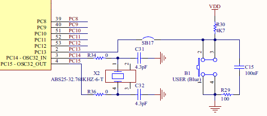
Again, we start with the board schematics. The user button is a switch that connects PC13 pin to ground when pushed down. Otherwise, PC13 pin is held at high logic level by means of the pull-up resistor R30.
In order to interface the push-button, we will write two functions:
- A function to initialize PC13 as an input pin
- A function that return the state of the button (0 for released, 1 for pushed)
You can add those functions in bsp.rs, below LED functions.
/*
 * bsp_pb_init()
 * Initialize Push-Button pin (PC13) as input without Pull-up/Pull-down
 */

pub fn bsp_pb_init(peripherals: &Peripherals) {
    let rcc = &peripherals.RCC;
    let gpioc = &peripherals.GPIOC;

    // Enable GPIOC clock
    rcc.ahbenr.modify(|_, w| w.iopcen().enabled());

    // Configure PC13 as input
    gpioc.moder.modify(|_, w| w.moder13().input());

    // Disable PC13 Pull-up/Pull-down
    gpioc.pupdr.modify(|_, w| w.pupdr13().floating());
}

/*
 * bsp_pb_get_state()
 * Returns the state of the button (0=released, 1=pressed)
 */

pub fn bsp_pb_get_state(peripherals: &Peripherals) -> bool {
    let gpioc = &peripherals.GPIOC;

    return gpioc.idr.read().idr13().is_low();
}
Then, test your new functions in main.rs:
mod bsp;

#[entry]
fn main() -> ! {
    // Get peripherals
    let peripherals = Peripherals::take().unwrap();

    // Configure System Clock
    let _fclk = system_clock_config(&peripherals).unwrap();

    // Initialize LED pin
    bsp::bsp_led_init(&peripherals);

    // Initialize User-Button pin
    bsp::bsp_pb_init(&peripherals);

    // Turn LED On
    bsp::bsp_led_on(&peripherals);

    // Turn LED Off
    bsp::bsp_led_off(&peripherals);

    loop {
        // Turn LED On if User-Button is pushed down
        if bsp::bsp_pb_get_state(&peripherals) {
            bsp::bsp_led_on(&peripherals);
        }
        // Otherwise turn LED Off
        else {
            bsp::bsp_led_off(&peripherals);
        }
    }
}
The LED is ON only when you press the user-button.
5. Summary
In this tutorial, we have written simple drivers for both LED and user-button. Associated functions manipulate GPIOs with both input and output configurations.