
1. Preparing the project
This tutorial is a simple introduction to power saving approaches. As an application example, we will use the Digital Filter project.
Let us first review the important pieces of code you need.
- The timebase should be tuned for 10ms period between update interrupts:
/*
 * BSP_TIMER_Timebase_Init()
 * TIM6 at 48MHz
 * Prescaler   = 48000  -> Counting frequency is 1kHz
 * Auto-reload = 10 	-> Update period is 10ms
 */
void BSP_TIMER_Timebase_Init()
{
	// Enable TIM6 clock
	RCC->APB1ENR |= RCC_APB1ENR_TIM6EN;

	// Reset TIM6 configuration
	TIM6->CR1 = 0x0000;
	TIM6->CR2 = 0x0000;

	// Set TIM6 prescaler
	// Fck = 48MHz -> /48000 = 1kHz counting frequency
	TIM6->PSC = (uint16_t) 48000 -1;

	// Set TIM6 auto-reload register for 10ms
	TIM6->ARR = (uint16_t) 10 -1;

	// Enable auto-reload preload
	TIM6->CR1 |= TIM_CR1_ARPE;

	// Enable Interrupt upon Update Event
	TIM6->DIER |= TIM_DIER_UIE;

	// Start TIM6 counter
	TIM6->CR1 |= TIM_CR1_CEN;
}
- The DAC is initialized for single channel operation (PA4) with no interrupt or DMA:
/*
 * DAC_Init()
 * Initialize DAC for a single output
 * on channel 1 -> pin PA4
 */

void BSP_DAC_Init()
{
	// Enable GPIOA clock
	RCC->AHBENR |= RCC_AHBENR_GPIOAEN;

	// Configure pin PA4 as analog
	GPIOA->MODER &= ~GPIO_MODER_MODER4_Msk;
	GPIOA->MODER |= (0x03 <<GPIO_MODER_MODER4_Pos);

	// Enable DAC clock
	RCC->APB1ENR |= RCC_APB1ENR_DACEN;

	// Reset DAC configuration
	DAC->CR = 0x00000000;

	// Enable Channel 1
	DAC->CR |= DAC_CR_EN1;
}
- The ADC is also initialized for single channel (PC1) operation with no interrupt or DMA:
/*
 * ADC_Init()
 * Initialize ADC for single channel conversion
 * - Channel 11 -> pin PC1
 */

void BSP_ADC_Init()
{
	// Enable GPIOC clock
	RCC->AHBENR |= RCC_AHBENR_GPIOCEN;

	// Configure pin PC1 as analog
	GPIOC->MODER &= ~(GPIO_MODER_MODER1_Msk);
	GPIOC->MODER |= (0x03 <<GPIO_MODER_MODER1_Pos);

	// Enable ADC clock
	RCC->APB2ENR |= RCC_APB2ENR_ADC1EN;

	// Reset ADC configuration
	ADC1->CR 	= 0x00000000;
	ADC1->CFGR1  = 0x00000000;
	ADC1->CFGR2  = 0x00000000;
	ADC1->CHSELR = 0x00000000;

	// Enable 12-bit resolution, continuous conversion mode
	ADC1->CFGR1 |= (0x00 <<ADC_CFGR1_RES_Pos) | ADC_CFGR1_CONT;

	// Select PCLK/2 as ADC clock
	ADC1->CFGR2 |= (0x01 <<ADC_CFGR2_CKMODE_Pos);

	// Set sampling time to 28.5 ADC clock cycles
	ADC1->SMPR = 0x03;

	// Select channel 11
	ADC1->CHSELR |= ADC_CHSELR_CHSEL11;

	// Enable ADC
	ADC1->CR |= ADC_CR_ADEN;

	// Start conversion
	ADC1->CR |= ADC_CR_ADSTART;
}
- And the main() function implements the filter operation with floating point arithmetic:
...
uint8_t    timebase_irq = 0;
uint16_t   in, out;
...

// Main program
int main()
{
	float c1, c2;	// Filter coefs
	float x = 0;	// Filter input
	float y = 0;	// Filter output

	// Configure System Clock
        SystemClock_Config();

	// Initialize 10ms timebase
	BSP_TIMER_Timebase_Init();
	BSP_NVIC_Init();

	// Initialize ADC
	BSP_ADC_Init();

	// Initialize DAC
	BSP_DAC_Init();

	// Initialize LED pin
	BSP_LED_Init();

	// Setup filter coefs
	c1 = 0.11765f;
	c2 = 0.88235;

	// Main loop
	while(1)
	{
		// Do every 10ms
		if (timebase_irq == 1)
		{
			// Start measure
			BSP_LED_On();

			// Input signal <-- ADC
			while ( (ADC1->ISR & ADC_ISR_EOC) != ADC_ISR_EOC );
			in = ADC1->DR;

			// Filter stage
			x = (float)in;
			y = (c1*x) + (c2*y);
			out = (uint16_t)y;

			// Output signal --> DAC
			DAC->DHR12R1 = out;

			// Stop measure
			BSP_LED_Off();
			timebase_irq = 0;
		}
	}
}
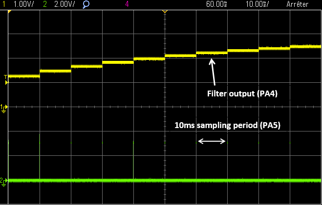
Make sure you have a working application with a new sample calculated every 10ms. You can probe PA5 (LED pin) to see the sampling period:
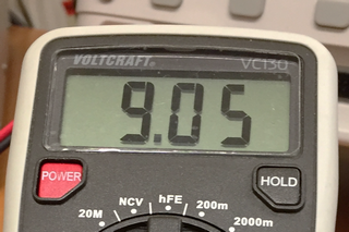
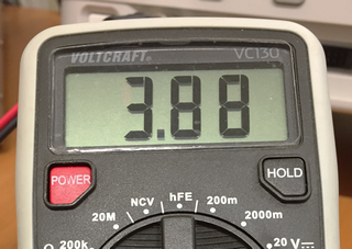
You can easily measure the current drown by the MCU by wiring an amperemeter in place of JP6 (IDD) jumper as shown in the picture below:
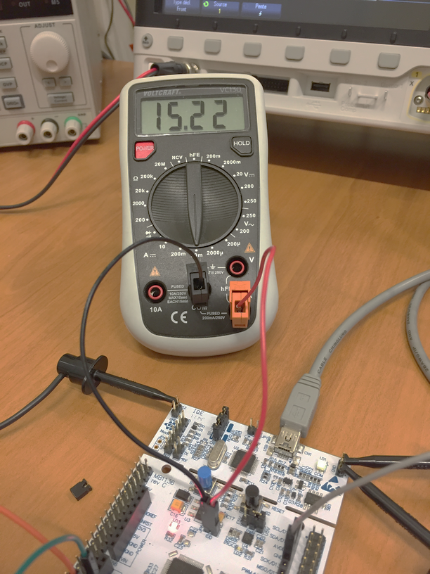
Our filter application is drawing about 15mA of current under 3.3V giving about 50mW of power consumption in its initial implementation.
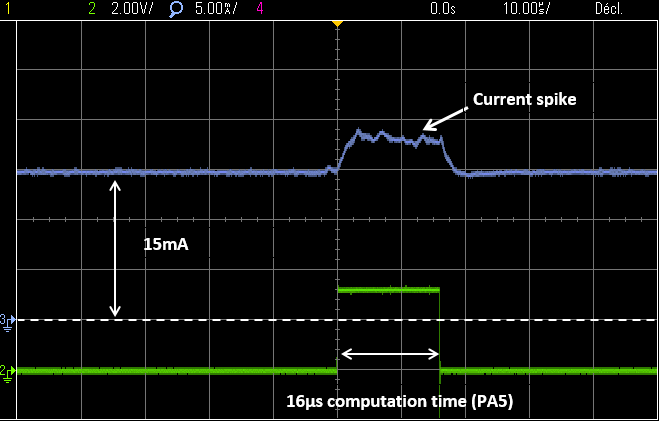
The screenshots below are obtained by using a current probe on JP6 connected to oscilloscope. You don’t have such probe (and it's quite expensive), so just look at the results below to gain understanding of what appends.
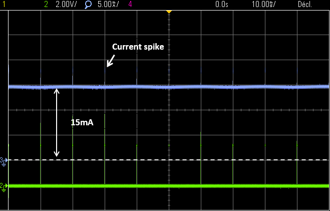
We compute a sample every 10ms. The time spent waiting for next sample is almost 10ms since the filter computation time is only 16µs.
While waiting for the next interruption, the current consumption is 15mA. During the filter processing code execution, we have a small current increase up to 18mA, but it is so short that it doesn’t count much in the average current provided by the ampere meter. One can assume that this current overhead is related to LED lightning.
 |
 Commit name "Saving power - Step #0" Commit name "Saving power - Step #0" Push onto Gitlab Push onto Gitlab |
Let-us see how we can do better…
2. Using Sleep mode
Sleep mode is the first of three-available low-power modes, namely: Sleep, Stop, Standby.
In Sleep mode, only the CPU clock is stopped. The execution resumes as soon as an event or an interruption occurs. It is therefore very simple to use in our context. Let-us sleep the CPU between two consecutive timer interrupts. This is done by calling the __WFI() (Wait For Interrupt) CMSIS function:
        // Main loop
	while(1)
	{
		// Do every 10ms
		if (timebase_irq == 1)
		{
			// Start measure
			BSP_LED_On();

			// Input signal <-- ADC
			while ( (ADC1->ISR & ADC_ISR_EOC) != ADC_ISR_EOC );
			in = ADC1->DR;

			// Filter stage
			x = (float)in;
			y = (c1*x) + (c2*y);
			out = (uint16_t)y;

			// Output signal --> DAC
			DAC->DHR12R1 = out;

			// Stop measure
			BSP_LED_Off();
			timebase_irq = 0;

			// Go into Sleep mode
			__WFI();
		}
	}
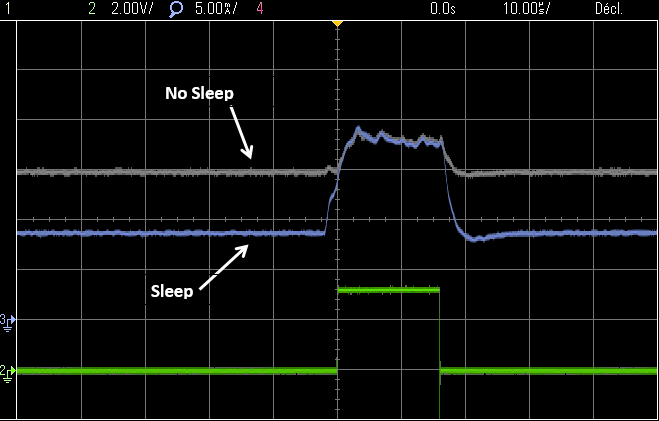
You should gain immediate benefits on the current consumption:
A closer look confirms what was expected. The power consumption is reduced during the waiting time (between samples) and has not changed during the computation time:
|
Commit name "Saving power - Step #1" Push onto Gitlab |
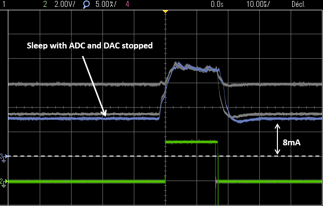
Again, Sleep mode stops the CPU clock. But it doesn’t stop peripherals clock. Here, we need TIM6 to generate the sampling period interrupt so we cannot stop it. On the contrary, we do not need the DAC and ADC working while waiting for the next sample to compute. We can stop these peripherals before entering the Sleep mode.
Try the code below:
	// Main loop
	while(1)
	{
		// Do every 10ms
		if (timebase_irq == 1)
		{
			// Start measure
			BSP_LED_On();

			// Enable DAC & ADC
			RCC->APB1ENR |= RCC_APB1ENR_DACEN;
			RCC->APB2ENR |= RCC_APB2ENR_ADC1EN;
			ADC1->CR |= ADC_CR_ADEN;

			// Input signal <-- ADC
			while ( (ADC1->ISR & ADC_ISR_EOC) != ADC_ISR_EOC );
			in = ADC1->DR;

			// Filter stage
			x = (float)in;
			y = (c1*x) + (c2*y);
			out = (uint16_t)y;

			// Output signal --> DAC
			DAC->DHR12R1 = out;

			// Stop measure
			BSP_LED_Off();
			timebase_irq = 0;

			// Disable DAC & ADC
			ADC1->CR &= ~ADC_CR_ADEN;
			RCC->APB2ENR &= ~RCC_APB2ENR_ADC1EN;
			RCC->APB1ENR &= ~RCC_APB1ENR_DACEN;

			// Go into Sleep mode
			__WFI();
		}
	}
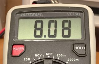
A slight improvement (10% still) should be there:
|
Commit name "Saving power - Step #2" Push onto Gitlab |
3. Slowing-down clock frequency
The application waits 10ms between samples and processing time is a very short 16µs. Do we really need a processor working at 48MHz clock speed?
Well, no!
Something very simple to try is to comment the SystemClock_Config() function call. Doing so, the CPU will work with the default clock config using HSI at 8MHz.
	// Configure System Clock
	// SystemClock_Config();
Of course, you’ll need to review the timebase settings according to the new clock frequency to keep a 10ms sampling period:
void BSP_TIMER_Timebase_Init()
{
	// Enable TIM6 clock
	RCC->APB1ENR |= RCC_APB1ENR_TIM6EN;

	// Reset TIM6 configuration
	TIM6->CR1 = 0x0000;
	TIM6->CR2 = 0x0000;

	// Set TIM6 prescaler
	// Fck = 8MHz -> /8000 = 1kHz counting frequency
	TIM6->PSC = (uint16_t) 8000 -1;

	// Set TIM6 auto-reload register for 10ms
	TIM6->ARR = (uint16_t) 10 -1;

	// Enable auto-reload preload
	TIM6->CR1 |= TIM_CR1_ARPE;

	// Enable Interrupt upon Update Event
	TIM6->DIER |= TIM_DIER_UIE;

	// Start TIM6 counter
	TIM6->CR1 |= TIM_CR1_CEN;
}
Improvement should be significant this time:
You can make sure that the filter works just as fine as before. It should.
Screenshot below illustrates what changed by slowing-down the system clock. Obviously, computation time is now about 6x longer, but still fits very comfortably within our 10ms sampling period. A global power consumption reduction is observed:
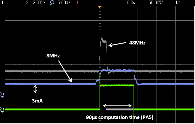
With a 90µs processing time, we have further room to reduce the system clock. You can try this:
	// Configure System Clock
	// SystemClock_Config();

	// Set HPRE to /16 -> 500kHz MCU clock
	RCC->CFGR |= RCC_CFGR_HPRE_DIV16;
With the associated timebase tuning:
void BSP_TIMER_Timebase_Init()
{
	// Enable TIM6 clock
	RCC->APB1ENR |= RCC_APB1ENR_TIM6EN;

	// Reset TIM6 configuration
	TIM6->CR1 = 0x0000;
	TIM6->CR2 = 0x0000;

	// Set TIM6 prescaler
	// Fck = 500kHz -> /500 = 1kHz counting frequency
	TIM6->PSC = (uint16_t) 500 -1;

	// Set TIM6 auto-reload register for 10ms
	TIM6->ARR = (uint16_t) 10 -1;

	// Enable auto-reload preload
	TIM6->CR1 |= TIM_CR1_ARPE;

	// Enable Interrupt upon Update Event
	TIM6->DIER |= TIM_DIER_UIE;

	// Start TIM6 counter
	TIM6->CR1 |= TIM_CR1_CEN;
}
You will get a slight improvement, but not very much.
|
Commit name "Saving power - Step #3" Push onto Gitlab |
4. Other improvements
With a lower clock frequency, the time spent doing the filter calculation increases and now represents a part of the sampling period that is no more negligible. Let us focus on something simple we could improve…
The pin that we use to measure processing time is the LED pin. Lightning a LED costs in term of power consumption.
We could rather use another pin with no associated LED. Let-us write a function in order to use PA6 for our measurement purpose. Add the following to bsp.c:
/*
 * BSP_DBG_Pin_Init()
 * Initialize Debug pin (PA6) as a High-Speed Push-Pull output
 * Set pin initial state to OFF
 */
void BSP_DBG_Pin_Init()
{
	// Enable GPIOA clock
	RCC->AHBENR |= RCC_AHBENR_GPIOAEN;

	// Configure PA6 as output
	GPIOA->MODER &= ~GPIO_MODER_MODER6_Msk;
	GPIOA->MODER |= (0x01 <<GPIO_MODER_MODER6_Pos);

	// Configure PA6 as Push-Pull output
	GPIOA->OTYPER &= ~GPIO_OTYPER_OT_6;

	// Configure PA6 as High-Speed Output
	GPIOA->OSPEEDR &= ~GPIO_OSPEEDR_OSPEEDR6_Msk;
	GPIOA->OSPEEDR |= (0x03 <<GPIO_OSPEEDR_OSPEEDR6_Pos);

	// Disable PA6 Pull-up/Pull-down
	GPIOA->PUPDR &= ~GPIO_PUPDR_PUPDR6_Msk;

	// Set Initial State OFF
	GPIOA->BSRR |= GPIO_BSRR_BR_6;
}
Do not forget to add the function prototype in bsp.h. Then let us use this:
// Main program
int main()
{
	...
	// Initialize Debug pin
	//BSP_LED_Init();
	BSP_DBG_Pin_Init();
	...

	// Main loop
	while(1)
	{
		// Do every 10ms
		if (timebase_irq == 1)
		{
			// Start measure
			//BSP_LED_On();
			GPIOA->BSRR = GPIO_BSRR_BS_6;

			...

			// Stop measure
			//BSP_LED_Off();
			GPIOA->BSRR = GPIO_BSRR_BR_6;

			...

			// Go into Sleep mode
			__WFI();
		}
	}
}
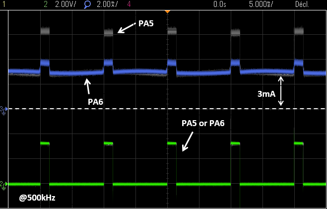
Again, a small improvement is observed:
That’s actually 2mA that have been saved during the filter processing time:
|
Commit name "Saving power - Step #4" Push onto Gitlab |
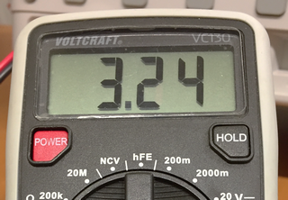
5. Summary
We’ve started with a filter application drowning a 15mA current. Using the Sleep mode and slowing the system clock frequency from 48MHz to 500kHz we were able to decrease the current consumption down to 3.2mA without any loss in the application performance.
In terms of power, it is a shift from 50mW to 10mW, or a battery life 5 times longer, for the very same service.
Think about it… Power and energy saving is where actual and future challenges are.
Add new comment