
1. Multi-Channel ADC with DMA
DMA is very useful when working on multi-channel ADC conversion. If you enable more than one ADC channel, each channel conversion result override the previous one in the ADC data register. You therefore need a mechanism to collect conversion result as soon as it is ready, and before the new one arrives.
You may use interruptions of course, but DMA is far more interesting because you can configure data transfer directly into a memory array without any load on CPU.
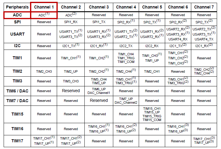
According to the table below, ADC is connected to DMA Channel 1:
Edit the BSP_ADC_Init() function in order to add a DMA functionality. To better illustrate the matter, ADC is now configured to perform a 3-Channels conversion:
- Channel 11 on PC1
- Channel 12 on PC2
- Channel 13 on PC3
Code is below:
/*
 * ADC_Init()
 * Initialize ADC for 3 channels conversion with DMA
 * - Channel 11 -> pin PC1
 * - Channel 12 -> pin PC2
 * - Channel 13 -> pin PC3
 */

extern uint16_t	adc_dma_buffer[3];

void BSP_ADC_Init()
{
	// Enable GPIOC clock
	RCC->AHBENR |= RCC_AHBENR_GPIOCEN;

	// Configure pin PC1, PC2, PC3 as analog
	GPIOC->MODER &= ~(GPIO_MODER_MODER1_Msk | GPIO_MODER_MODER2_Msk | GPIO_MODER_MODER3_Msk);

	GPIOC->MODER |=	(0x03 <<GPIO_MODER_MODER1_Pos) | (0x03 <<GPIO_MODER_MODER2_Pos) | (0x03 <<GPIO_MODER_MODER3_Pos);

	// Enable ADC clock
	RCC->APB2ENR |= RCC_APB2ENR_ADC1EN;

	// Reset ADC configuration
	ADC1->CR 	= 0x00000000;
	ADC1->CFGR1  = 0x00000000;
	ADC1->CFGR2  = 0x00000000;
	ADC1->CHSELR = 0x00000000;

	// Enable continuous conversion mode
	ADC1->CFGR1 |= ADC_CFGR1_CONT;

	// 12-bit resolution
	ADC1->CFGR1 |= (0x00 <<ADC_CFGR1_RES_Pos);

	// Select PCLK/2 as ADC clock
	ADC1->CFGR2 |= (0x01 <<ADC_CFGR2_CKMODE_Pos);

	// Set sampling time to 28.5 ADC clock cycles
	ADC1->SMPR = 0x03;

	// Select channel 11, 12, 13
	ADC1->CHSELR |= ADC_CHSELR_CHSEL11 | ADC_CHSELR_CHSEL12 | ADC_CHSELR_CHSEL13;

	// Start DMA clock
	RCC->AHBENR |= RCC_AHBENR_DMA1EN;

	// Reset DMA1 Channel 1 configuration
	DMA1_Channel1->CCR = 0x00000000;

	// Configure DMA1 Channel 1
	// Peripheral -> Memory
	// Peripheral is 16-bit, no increment
	// Memory is 16-bit, increment
	// Circular mode

	DMA1_Channel1->CCR |= (0x01 <<DMA_CCR_PSIZE_Pos) | (0x01 <<DMA_CCR_MSIZE_Pos) | DMA_CCR_MINC | DMA_CCR_CIRC;

	// Peripheral is ADC1 DR
	DMA1_Channel1->CPAR = (uint32_t)&ADC1->DR;

	// Memory is adc_dma_buffer
	DMA1_Channel1->CMAR = (uint32_t)adc_dma_buffer;

	// Set Memory Buffer size
	DMA1_Channel1->CNDTR = 3;

	// Enable DMA1 Channel 1
	DMA1_Channel1->CCR |= DMA_CCR_EN;

	// Enable ADC DMA Request in circular mode
	ADC1->CFGR1 |= ADC_CFGR1_DMACFG | ADC_CFGR1_DMAEN;

	// Enable ADC
	ADC1->CR |= ADC_CR_ADEN;

	// Start conversion
	ADC1->CR |= ADC_CR_ADSTART;
}
2. Testing
Edit the BSP_TIMER_Timebase_Init() function to get an update interrupt every 100ms:
/*
 * BSP_TIMER_Timebase_Init()
 * TIM6 at 48MHz
 * Prescaler   = 48000 -> Counting period = 1ms
 * Auto-reload = 100   -> Update period   = 100ms
 */

void BSP_TIMER_Timebase_Init()
{
	// Enable TIM6 clock
	RCC->APB1ENR |= RCC_APB1ENR_TIM6EN;

	// Reset TIM6 configuration
	TIM6->CR1 = 0x0000;
	TIM6->CR2 = 0x0000;

	// Set TIM6 prescaler
	// Fck = 48MHz -> /48000 = 1KHz counting frequency
	TIM6->PSC = (uint16_t) 48000 -1;

	// Set TIM6 auto-reload register for 100ms
	TIM6->ARR = (uint16_t) 100 -1;

	// Enable auto-reload preload
	TIM6->CR1 |= TIM_CR1_ARPE;

	// Enable Interrupt upon Update Event
	TIM6->DIER |= TIM_DIER_UIE;

	// Start TIM6 counter
	TIM6->CR1 |= TIM_CR1_CEN;
}
Then edit main.c as follows. Basically, you need to declare the global variable adc_dma_buffer[3] and then call the BSP_ADC_Init() function. It is all you really need. Other calls are just for the console and timer to print data every 100ms.
// Global variables
...
uint16_t	adc_dma_buffer[3];

// Main program
int main()
{
	// Configure System Clock
	SystemClock_Config();

	// Initialize Console
	BSP_Console_Init();
	my_printf("Console Ready!\r\n");

	// Initialize 1s timebase
	BSP_TIMER_Timebase_Init();
	BSP_NVIC_Init();

	// Initialize ADC with DMA
	BSP_ADC_Init();

	// Main loop
	while(1)
	{
		// Do every 100ms
		if(timebase_irq == 1)
		{
			// Print ADC conversion results
			my_printf("Ch11=%04d | Ch12=%04d | Ch13=%04d\r", adc_dma_buffer[0], adc_dma_buffer[1], adc_dma_buffer[2]);

			// Reset timebase flag
			timebase_irq = 0;
		}
	}
}
The main loop is just a periodic print of adc_dma_buffer[3] content. The mechanism of getting ADC data into this array is done in the background by ADC and DMA peripherals, without any CPU intervention.
To further test the application, one should wire potentiometers to PC1, PC2, PC3 pins and monitor the ADC conversion results with STM32CubeMonitor.
 |
 Commit name "Multi-channel ADC with DMA" Commit name "Multi-channel ADC with DMA" Push onto Gitlab Push onto Gitlab |
3. Summary
In this tutorial, you have learned how to perform a Multi-Channels ADC conversion and collect results directly in memory without any load on the CPU thanks to DMA.
Add new comment