
Before we go on with this fourth version of the Hello World application, let us summarize what we've seen so far.
- The first Hello World #1 example was built within STM32CubeIDE using CubeMX graphical peripheral configuration tool and HAL libraries. The purpose of that tutorial was to introduce the ST way to get started.
- The second Hello World #2 example was edited and built with no IDE, using the sole MCU ARM GCC toolchain command line interface (CLI) and a single minimalist main.c source file. The purpose of that tutorial was to make the point that actually no IDE is absolutely necessary to write, build and flash programs into the MCU device. Yet, although possible with no IDE, I didn't dare to address detailed debugging here.
- The third Hello World #3 example was actually a simple clone of the previous project, built and debugged within STM32CubeIDE. This example has been used for a walkthrough in the full-featured IDE debugger. Doing that we've seen that this project lacks important stuff for the code to behave properly.
So what's coming next. In this fourth and last Hello World #4 example, let us create from scratch a minimal project that include everything we actually need to start programming STM32 devices, with no Hardware Abstraction Layer yet with some additional headers and initialization functions that are quite welcome.
With minor adaptations, you may consider this tutorial as a reference for starting new projects with any STM32 devices.
1. Create a New Project
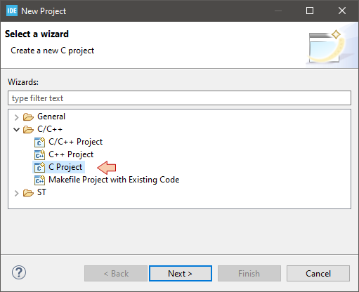
Using the Project Explorer, close all projects that have been left open. The first steps are the same as before. From the main menu: File→New→Project.
In the New Project dialog, select C Project.
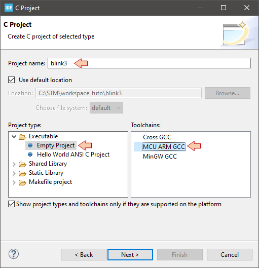
In the C Project dialog, provide a name for the project ("blink3" for instance) and choose Empty Project as project type and MCU ARM GCC for the toolchain. Then click Next and proceed with MCU selection as before (see tutorial 1.4).
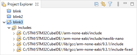
An empty "blink3" project is created and added to your workspace with the usual set of include paths for the C standard libraries:
2. Prepare the project file structure
Using the ![]() project contextual menu (Right-Click), and then:
project contextual menu (Right-Click), and then:
- New →
 Source Folder
 - New →
 Folder
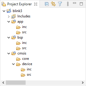
Create the following folder structure :
 |
|
Note that this folder structure is only a suggestion. If you know what you are doing, you can organize files the way you want and even put everything below root folder, although not recommended…
As your project grows, the number of source files can become really big. You need a clean file structure that you know and understand well to navigate comfortably between sources. The sooner you get familiar with your choice of folder structure, the better. Even for small projects.
3. Get the CMSIS files
An STM32 microcontroller, just like many others MCUs from several silicon vendors, is designed around an ARM Cortex-M core processor. ARM-based microcontroller come with a set of source files as defined by ARM under the Cortex Microcontroller Software Interface Standard (CMSIS) specification.

"The Cortex Microcontroller Software Interface Standard (CMSIS) is a vendor-independent hardware abstraction layer for microcontrollers that are based on Arm Cortex processors. CMSIS defines generic tool interfaces and enables consistent device support. The CMSIS software interfaces simplify software reuse, reduce the learning curve for microcontroller developers, and improve time to market for new devices.
CMSIS provides interfaces to processor and peripherals, real-time operating systems, and middleware components. CMSIS includes a delivery mechanism for devices, boards, and software, and enables the combination of software components from multiple vendors."
https://developer.arm.com/tools-and-software/embedded/cmsis
Practically, it is only few files you have to include in your project structure. These files are illustrated below :
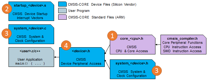
In order to get up-to-date CMSIS source files, a good option is to download the latest release of STM32 Cube libraries for the targeted device familly (STM32F0 here). It comes as a pretty big package including HAL libraries, but do not worry, we will only pick-up few files from this package.
You can get the STM32F0 Cube library from ST website (don't do it now) : https://www.st.com/en/embedded-software/stm32cubef0.html (Version 1.11.2 at time of writing).
If you started these tutorials from the beginning, you probably already downloaded the STM32F0 Cube library because CubeMX, involved in the first Hello World demo, did it for you. What you need, is to know where it has landed on your hard drive.
Open Window → Preferences and select STM32Cube/Firmware Updater category. You'll find the location of downloaded libraries there.
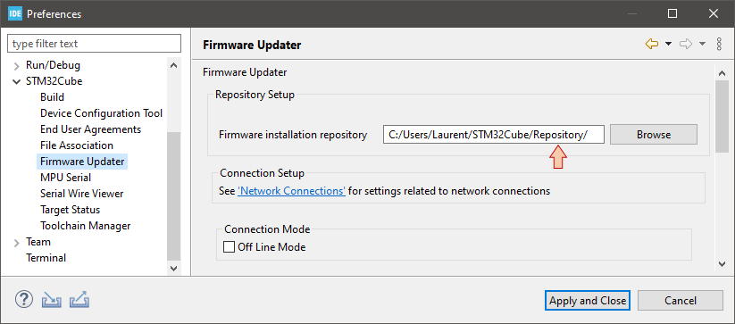
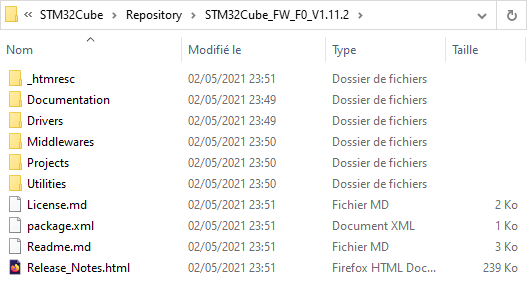
Click Cancel and then use your OS file explorer to navigate into that location and open the STM32Cube_FW_F0_Vx.xx.x folder:
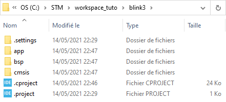
In another window, open your project folder located in your workspace folder:
Then copy/paste the following files, from the Cube library, into your project folders. Numbered files correspond to those in the CMSIS specification above. To these files, we just add the linker script (6) and a set of source files for interrupts handling (5). The latter is not necessary right now, but has been included here for completeness and further use.
| # | File(s) | Source folder | Destination folder |
| 1 | *.h | \Drivers\CMSIS\Include\ | \cmsis\core\ |
| 2 | startup_stm32f072xb.s | \Drivers\CMSIS\Device\ST\STM32F0xx\ Source\Templates\gcc | \cmsis\device\src |
| 3 | system_stm32f0xx.h | \Drivers\CMSIS\Device\ST\STM32F0xx\Include | \cmsis\device\inc |
| 3 | system_stm32f0xx.c | \Drivers\CMSIS\Device\ST\STM32F0xx\ Source\Templates | \cmsis\device\src |
| 4 | stm32f0xx.h, stm32f072xb.h | \Drivers\CMSIS\Device\ST\STM32F0xx\Include | \cmsis\device\inc |
| 5 | stm32f0xx_it.h | \Projects\STM32F072RB-Nucleo\Templates\Inc | \app\inc |
| 5 | stm32f0xx_it.c | \Projects\STM32F072RB-Nucleo\Templates\Src | \app\src |
| 6 | STM32F072RBTx_FLASH.ld | \Projects\STM32F072RB-Nucleo\Templates\SW4STM32\STM32F072RB-Nucleo | \ |
If you are working with a device other than the STM32F072RB, just adapt the previous table to your needs… All ST Cube libraries share the same file structure and naming convention.
Back into Eclipse, Right-Click on the project name in the Project Explorer and select Refresh (or press F5). Your project structure now should be:
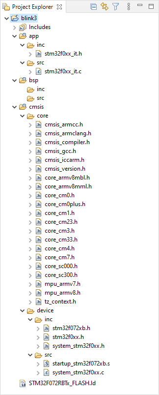
Some more explanations about files we've just added to the project:
- The core headers are required to access dedicated CPU functionalities, which are not part of ST hardware. For instance, we use core CPU functions to configure the system timer (Systick), the Nested Vector Interrupt Controller (NVIC), and Low-Power modes.
- STM32F0 headers (stm32f0xx.h, stm32f072xb.h) contain definitions (aliases) for all STM32 peripheral registers and their content. It is not a library, it is basically nothing more than a huge list of #define. It allows calling a register and associated bit by names instead of addresses. For example, the code below we used to toggle the LED state (pin PA5) in previous labs:
*(int *)0x48000014 ^= 0x00000020U;
can now be written:
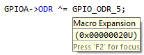
GPIOA->ODR ^= GPIO_ODR_5;
which is exactly same code, as there are just a #define behind GPIOA, ODR, GPIO_ODR_5 labels. Still, it makes code writing and reading way more comfortable. When hovering the mouse over a #defined symbol, you get a bubble info that provides the definition:
These headers also include data types based on <stdint.h> that we will use instead of standard C types for integer numbers:
| C types | Embedded types |
|---|---|
| char | int8_t |
| unsigned char | uint8_t |
| short | int16_t |
| unsigned short | uint16_t |
| int | int32_t |
| unsigned int | uint32_t |
- system_stm32.c and system_stm32.h provide few functions and macros you may want to use. In particular, the default clock settings are defined here and called from the startup routine.
- The startup code startup_stm32f072xb.s, which implements proper variable initialization.
- The associated linker script STM32F072RBTx_FLASH.ld
4. Add application files
If you take a look in the startup_stm32f072xb.s assembly routine, which is the very first code that is executed at startup, you'll see that after performing some initializations, there is a call to three functions, the last one being main, which is not supposed to return because if it happens, the startup code catches the application into an empty infinite loop.
This is where main() function is defined as the application entry point. You may change that name if you like, but I would suggest you do not.
/* Call the clock system intitialization function.*/
  bl  SystemInit
/* Call static constructors */
  bl __libc_init_array
/* Call the application's entry point.*/
  bl main

LoopForever:
    b LoopForever
Well, we need to implement a main() function because so far, we don't have any.
- Right-Click on the app\src\ folder in the Project Explorer and choose New →
 Source File and add main.c to that folder
 - Right-Click on the app\inc\ folder in the Project Explorer and choose New →
 Header File and add main.h to that folder. It will be of no use in this example, but we'll have it for future needs.
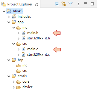
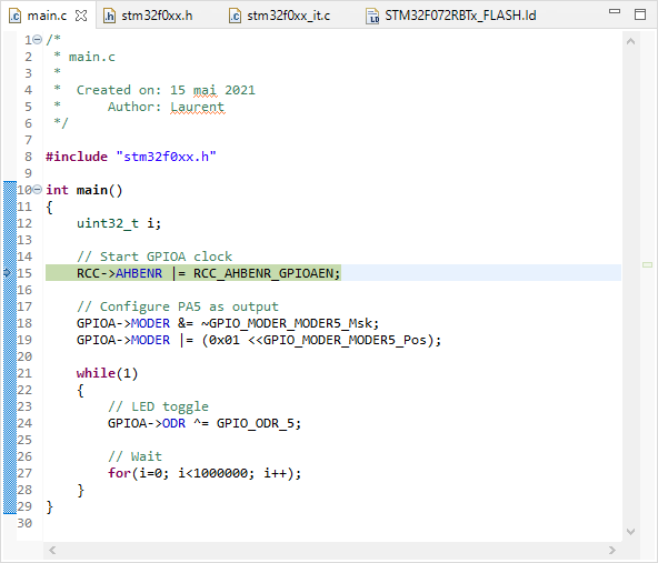
Then open main.c in the editor and let us rewrite the blinking demo, taking advantage of the device headers for a more meaningful code syntax:
/*
 * main.c
 *
 *  Created on: 15 mai 2021
 *      Author: Laurent
 */

#include "stm32f0xx.h"

int main()
{
	uint32_t i;

	// Start GPIOA clock
	RCC->AHBENR |= RCC_AHBENR_GPIOAEN;

	// Configure PA5 as output
	GPIOA->MODER &= ~GPIO_MODER_MODER5_Msk;
	GPIOA->MODER |= (0x01 <<GPIO_MODER_MODER5_Pos);

	while(1)
	{
		// LED toggle
		GPIOA->ODR ^= GPIO_ODR_5;

		// Wait
		for(i=0; i<100000; i++);
	}
}
Save all ![]() .
.
At this moment, if you try the build ![]() button, it won't work. We need to configure the build first.
button, it won't work. We need to configure the build first.
5. Setting project build properties
Right-Click on the project folder and select ![]() → Properties
→ Properties
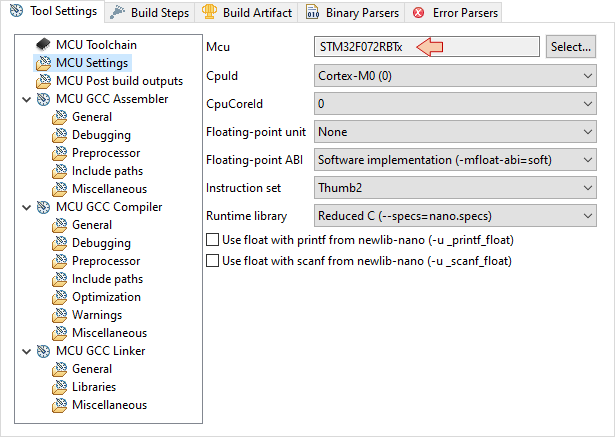
Select the C/C++ Build→Settings
- In the MCU Settings section, review the MCU fields for your target device:
- In the MCU GCC Linker\General section, edit the name of the linker script to match the one you've copied before:

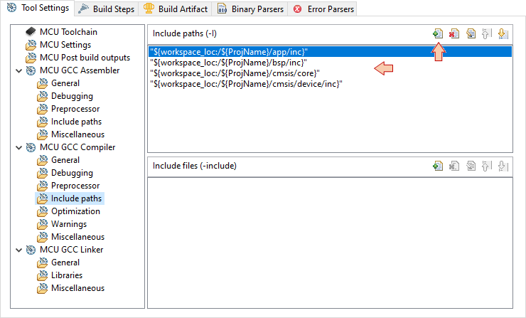
- In the MCU GCC Compiler\Include paths section, you must provide paths to all the header files (.h) in your project. In our example, we have headers in:
- /app/inc
- /bsp/inc
- /cmsis/core
- /cmsis/device/inc
Use the Add ![]() button and then browse the Workspace to select folders. Doing so will avoid mistakes.
button and then browse the Workspace to select folders. Doing so will avoid mistakes.
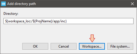
Make sure all 4 paths are defined as follows:
When you're done, click the Apply & Close button of the Properties dialog.
Try the build ![]() button and watch the console. You should get several errors. Scroll up to the first one:
button and watch the console. You should get several errors. Scroll up to the first one:
C:/STM/workspace_tuto/blink3/cmsis/device/inc/stm32f0xx.h:159:3: error: #error "Please select first the target STM32F0xx device used in your application (in stm32f0xx.h file)"
  159 |  #error "Please select first the target STM32F0xx device used in your application (in stm32f0xx.h file)"
      |   ^~~~~
This error is reported from within the stm32f0xx.h header:
#else
 #error "Please select first the target STM32F0xx device used in your application (in stm32f0xx.h file)"
#endif
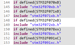
You'll notice that device headers #include above that line are actually all grayed-out, meaning that no header is in fact included. The reason is that you must select which particular device you want to target in this project.
There are 2 ways to to that:
- By editing the stm32f0xx.h header. You can either:
- Add this
#define STM32F072xBAt the beginning of the header
-
Or simply un-comment the following line:
/* #define STM32F072xB */ /*!< STM32F072x8, STM32F072xB Devices (STM32F072xx microcontrollers where the Flash memory ranges between 64 and 128 Kbytes) */
- Add this
- By adding a preprocessor symbol in the build configuration. I definitely recommend this method because it leaves ST headers clean from any modification so that you can reuse those in another project without troubles.
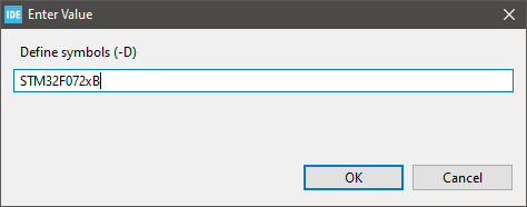
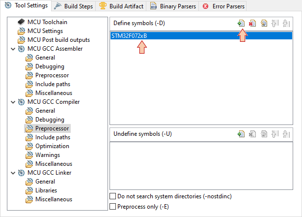
Go back to project properties ![]() → Properties, under C/C++ Build→Settings, and select the MCU GCC Compiler\Preprocessor section. In the Define symbols area, click the Add
→ Properties, under C/C++ Build→Settings, and select the MCU GCC Compiler\Preprocessor section. In the Define symbols area, click the Add ![]() button and edit the symbol you want to add:
button and edit the symbol you want to add:
Make sure the symbol has been added, and then Apply & Close the Properties dialog.
You can notice immediate effect in the stm32f0xx.h header. The stm32f072xb.h header is no more grayed-out!
We're almost done... One last thing to do is to comment the call to HAL_IncTick() function in the stm32f0xx_it.c file, as we're not using HAL libraries.
/**
  * @brief  This function handles SysTick Handler.
  * @param  None
  * @retval None
  */
void SysTick_Handler(void)
{
  // HAL_IncTick();   // <- Comment this line
}
Save all ![]() .
.
6. Build and debug
Hit the build ![]() button and perform the usual checks:
button and perform the usual checks:
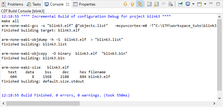
- watch the Console. The build should pass without any warning or error:
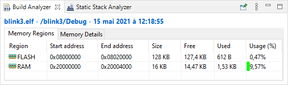
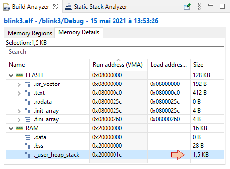
- Have a look on the Build Analyzer and check memory levels:
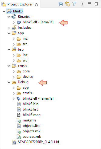
- Make sure binaries and debug data has been updated in the Project Explorer:
Then, move on to the Debug Configuration ![]() . You did this twice already, so I'm not going into the details anymore. Just setup the debug configuration as usual:
. You did this twice already, so I'm not going into the details anymore. Just setup the debug configuration as usual:
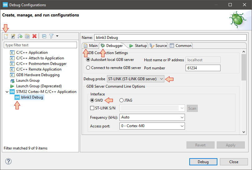
And then make sure that the debugger session launches with no problems:
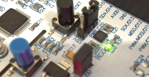
Finally try running the program with the usual debugger commands (![]() ,
, ![]() ,
, ![]() ), make sure the LED is still blinking...
), make sure the LED is still blinking...
... then exit the debug session ![]() . Well done!
. Well done!
7. Summary
In this tutorial, we've seen an approach to start new STM32 projects from scratch, using STM32CubeIDE while staying away from automatic templates and HAL libraries. Such approach should be portable across other IDEs if you like.
The so-prepared project is simple and robust, featuring:
- Full CMSIS layer including:
- Startup code with a complete interrupt vector table and variables (data, bss...) initialization routines
- System initialization functions
- Device headers enabling the use of embedded types and peripheral aliases instead of magic numbers
- A clean linker script
This approach to start new project is the one I promote. You should get used to start projects this way and see if you can adapt this methods to other STM32 devices.
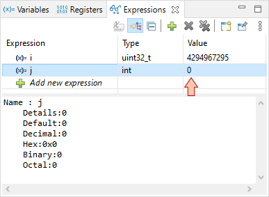
You can experiment variable initialization for instance, and make sure it now works as expected:
/* Global variable */
int j = 0;
The table below compares the memory footprint of the three Hello World demos we've experimented until now:
| Hello World #1 | Hello World #2, #3 | Hello World #4 | |
|---|---|---|---|
| FLASH | 5.04kB | 168B | 612B |
| RAM | 1.55kB | 0B | 1.53kB |
When compared to the Hello World #1, the Hello World #4 uses much less FLASH. Regarding RAM, one can wonder why the hell 1.53kB are still in use whereas no static or global variable has been declared.
In fact, that amount of RAM is not really used. It corresponds to an empty memory segment which is declared in the linker script in order to trigger a build error (alarm) in case there's no free memory left for this segment to be reserved (0x200 + 0x400 = 0x600 = 1.536kB):
/* Generate a link error if heap and stack don't fit into RAM */
_Min_Heap_Size  = 0x200;      	/* required amount of heap  */
_Min_Stack_Size = 0x400; 	/* required amount of stack */
Local variables such as i in the above example will be placed in that segment, just like any other variables with dynamically allocated memory. That's a safe practice indeed, because as we already discussed, the build report does not take into account the amount of memory required for local variables. In that respect, Hello World #1 and Hello World #4 are pretty much equivalent.
Add new comment